Small electric valve for shock-absorbing protecting torsion force

An electric valve and torque technology, applied in valve details, valve devices, engine components, etc., can solve the problems of actuator damage, equipment or system loss, valve leakage rate, etc., and achieve small opening torque, high pressure bearing characteristics, The effect of high pressure

Inactive Publication Date: 2011-08-10
张跃
View PDF0 Cites 0 Cited by
  • Summary
  • Abstract
  • Description
  • Claims
  • Application Information

AI Technical Summary

Problems solved by technology

[0002] At present, valves at home and abroad, including the products of world-renowned valve manufacturers, have the following defects in the function of their regulating valves: leakage, some medium still passes through the valve after it is closed, and it is necessary to manually close the stop valve. and other equipment or systems with strict requirements cause immeasurable losses
All kinds of valves generally have fatal structural defects: 1. The integral valve plate bears a large pressure. According to calculations, after an electric two-way valve with a caliber of DN150 is closed under a pressure difference of 0.8MPa, the valve plate bears a pressure of 1413kg. In other words, closing a DN150 electric two-way valve requires an external force of at least 1413kg. Such a huge pressure often leads to damage to the actuator. Therefore, the production model of the valve can only be controlled below DN150, and the power required for larger models is doubled. Increase, such as a valve with a diameter of DN200 requires a closing force of 2512kg
2. A balance hole is opened on the valve plate to reduce the pressure difference, so that the force required to open the valve is reduced. For example, the Siemens valve adopts this method, but because the balance hole directly leads to the pipeline and the working system, and this system is relatively balanced The hole is often very large, which not only fails to achieve the effect of balancing the pressure on both sides of the valve plate, but also makes the leakage rate of the already leaking valve larger

Method used


Image

  • Small electric valve for shock-absorbing protecting torsion force
  • Small electric valve for shock-absorbing protecting torsion force

Examples


Embodiment Construction

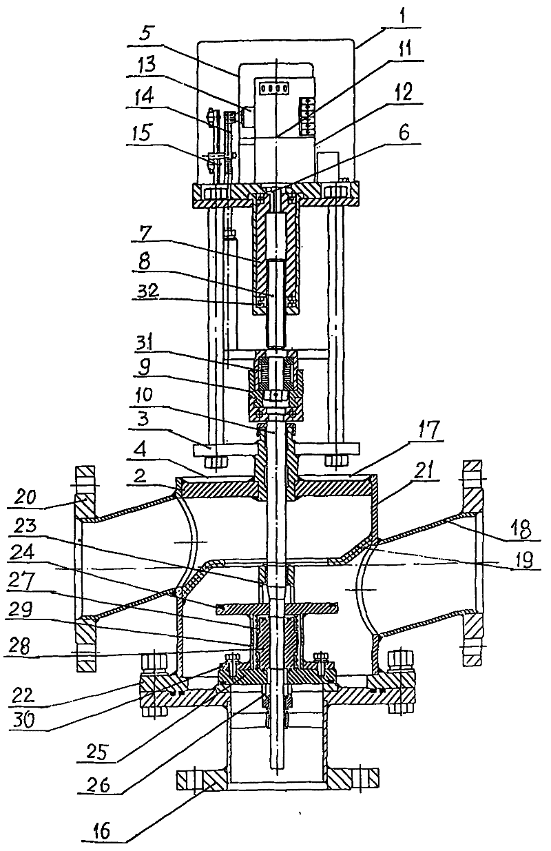
[0017] See figure 1 The present invention is composed of two parts of the actuator 1 and the valve body 2. The actuator 1 is installed and fixed on the valve seat 4 on the top of the valve body through the lower bracket plate 3, and the drive motor 5 of the actuator 1 is connected to the transmission through the hook key 6 The nut 7 is connected, and the two ends of the transmission nut 7 are equipped with plane thrust ball bearings 32, the torque is greatly reduced, the opening is easy and labor-saving, and the hand can be twisted. However, the traditional technology cannot be twisted by hand, and can only be opened by the oil pump. The transmission nut 7 It also cooperates with the drive screw 8 with T-threads to change the rotational movement of the drive motor 5 into the up and down movement of the drive screw 8. The drive screw is connected to the valve shaft 10 through a coupling 9, which is equipped with anti-shock and shock absorption. Butterfly spring 31, a position si...


PUM


Abstract

The invention relates to an electric valve with a shock absorption protection function and small torsion, which consists of two parts that are connected, namely, an actuating mechanism and a valve main body. A driving motor, a transmission nut, a transmission screw, a coupling and a valve shaft are in connection and transmission in sequence; the actuating mechanism is also internally provided with a position signal feedback device, an analog control device and an outage reduction device; the middle of a valve plate is provided with a pilot valve plate and a valve core spring, and the valve plate is provided with a sealing ring using polypropylene as base material; the two ends of the transmission nut are provided with a plane thrust ball bearing and a disc spring is arranged in the coupling. The valve has no leakage, can carry out automatic reduction in case of outage and reduce consumption, and is energy-saving, labor-saving and easy to open and close with advanced technology and excellent performance.

Description

Technical field: [0001] The invention relates to a valve in mechanical engineering, in particular to an electric valve with a small torque for shock absorption and protection. Background technique: [0002] At present, valves at home and abroad, including products from world-renowned valve manufacturers, have the following defects in their regulating valve functions: leakage, some medium still passes through the valve after the valve is closed, and the shut-off valve needs to be closed manually. If neglected, the bromine cooler will be Such demanding equipment or systems cause immeasurable losses. At the same time, most products have no power-off reset device. Only the Siemens valve has a power-off reset device for the oil pump compression return spring. Each time it is turned on, the valve needs to be opened by the huge return spring compressed by the oil pump. Elastic force closes the valve, and the oil pump is easily damaged and wastes energy. In addition. All kinds of valv...

Claims


Application Information

Patent Timeline
Patent Type & Authority Patents(China)
IPC IPC(8): F16K31/04F16K31/44
Inventor 张跃
Owner 张跃
Why Eureka
Try Eureka