
Wood plate compress-conveying mechanism

A transmission mechanism and board technology, applied in wood processing equipment, sawing components, manufacturing tools, etc., can solve the problems affecting the cutting of wood boards, difficult boards, clamping and transmission, etc., to meet the needs of processing and use, and improve efficiency and quality, the effect of high-efficiency compression transmission

Inactive Publication Date: 2016-08-17
于星杰
View PDF8 Cites 13 Cited by
  • Summary
  • Abstract
  • Description
  • Claims
  • Application Information

AI Technical Summary

Problems solved by technology

[0002] At present, due to its convenient processing and certain strength, wood is widely used in our production and life, and is closely related to each of us. Wood is used by us to build houses, decorate indoor environments, and make indoor furniture. During the process, according to the needs of wood use, it is necessary to evenly cut the wide planks into several wooden strips. During the cutting process of the existing planks, the planks are generally pushed by hand so that the planks can be cut evenly. In the process of pushing the wooden boards, it is difficult to push the wooden boards efficiently and accurately, which affects the need for cutting the wooden boards, and the labor intensity of the workers is relatively high. The existing wooden board transmission mechanism only places the wooden boards horizontally and then transmits them, so it is difficult to clamp the wooden boards Transmission makes it difficult for the wood board to be transferred to the next process for cutting, which affects the efficiency and quality of wood board production and processing, and cannot meet the needs of processing and use

Method used


Image

  • Wood plate compress-conveying mechanism
  • Wood plate compress-conveying mechanism

Examples


Embodiment Construction

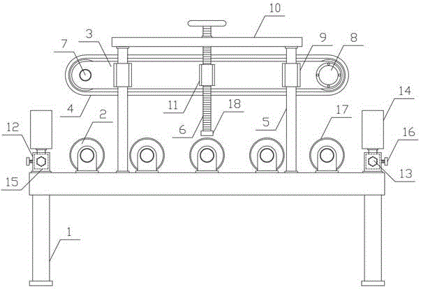
[0011] In order to further describe the present invention, a specific implementation of a plank pressing transmission mechanism will be further described below in conjunction with the accompanying drawings. The following examples are explanations of the present invention and the present invention is not limited to the following examples.

[0012] Such as figure 1 , figure 2 As shown, a plank pressing transmission mechanism of the present invention includes a fixed base 1, a guide roller 2, a pressing bracket 3, a conveyor belt 4, a lifting guide rod 5 and a lifting screw 6, and the upper side of the fixed base 1 is along the direction of plank transport. A plurality of material guide rollers 2 are connected by horizontal and uniform rotation in turn, and the upper and lower sides of the fixed base 1 are respectively provided with transmission limit mechanisms. Connected with a transmission roller 7, the conveyor belt 4 is horizontally arranged on the transmission roller 7, a...


PUM


Abstract

The invention discloses a wood plate compress-conveying mechanism and belongs to the field of wood processing mechanical equipment. The wood plate compress-conveying mechanism comprises a fixed base, guide rollers, a compressing support, a conveying belt, lifting guide rods and a lifting screw, the plurality of guide rollers are horizontally, evenly and rotatably connected onto the top of the fixed base along a wood plate conveying direction, conveying limit mechanisms are disposed on two sides of the upper portion of the fixed base respectively, the compressing support is horizontally disposed above the guide rollers, two ends of the compressing support are horizontally and rotatably connected with conveying rollers respectively, the conveying belt is horizontally disposed on the conveying rollers, a conveying motor drives the conveying rollers, two ends of one side of the compressing support are vertically provided with guide sleeves respectively, the lifting guide rods are vertically and downwardly passed through the guide sleeves and fixed to the top of the fixed base, the middle of one side of the compressing support is vertically provided with a lifting sleeve that is in threaded connection with the lifting screw. The wood plate compress-conveying mechanism is reasonable in structural design, can compress and convey wood plates efficiently, easily and accurately and meets the requirement for processing wood plates.

Description

technical field [0001] The invention belongs to the field of wood processing machinery and equipment, and in particular relates to a wood board pressing transmission mechanism. Background technique [0002] At present, due to its convenient processing and certain strength, wood is widely used in our production and life, and is closely related to each of us. Wood is used by us to build houses, decorate indoor environments, and make indoor furniture. During the process, according to the needs of wood use, it is necessary to evenly cut the wide planks into several wooden strips. During the cutting process of the existing planks, the planks are generally pushed by hand so that the planks can be cut evenly. In the process of pushing the wooden boards, it is difficult to push the wooden boards efficiently and accurately, which affects the need for cutting the wooden boards, and the labor intensity of the workers is relatively high. The existing wooden board transmission mechanism ...

Claims


Application Information

Patent Timeline
Patent Type & Authority Applications(China)
IPC IPC(8): B27B25/02B27B25/10B27B31/00
CPCB27B25/02B27B25/10B27B31/003
Inventor 於星杰
Owner 于星杰
Learn More