Turbulent agglomeration chamber and method for removing ultrafine particles using the agglomeration chamber

A turbulent and particle technology, applied in the field of turbulent agglomeration chamber, can solve the problems of increasing the complexity of the device, poor utilization of the vortex wake, and increasing the investment cost, and achieves the effect of simple shape, obvious diversion effect, and prevention of wall surface aggregation.

Inactive Publication Date: 2018-02-13
HEBEI UNIV OF TECH
View PDF6 Cites 0 Cited by
  • Summary
  • Abstract
  • Description
  • Claims
  • Application Information

AI Technical Summary

Problems solved by technology

The vortex used in this coalescer is a "+" cross-section blade, and the cross-shaped vortex has a better vortex generation effect. The disadvantage is that the resistance formed by such an arrangement is relatively large, resulting in poor utilization of the vortex wake generated after the vortex. and cause large particles to settle in the agglomeration chamber
The purpose of the pre-charged section of the device is to charge the particles. In the subsequent mixing section, due to the mutual attraction of positive and negative charges, the interaction between the particles is very intense, but such a structure increases the complexity of the device. Fixed electrodes Unsaturated polyester resin glass mat boards are used as the connecting parts of the boards, which also increases the investment cost

Method used


Image

  • Turbulent agglomeration chamber and method for removing ultrafine particles using the agglomeration chamber
  • Turbulent agglomeration chamber and method for removing ultrafine particles using the agglomeration chamber
  • Turbulent agglomeration chamber and method for removing ultrafine particles using the agglomeration chamber

Examples


Embodiment 1

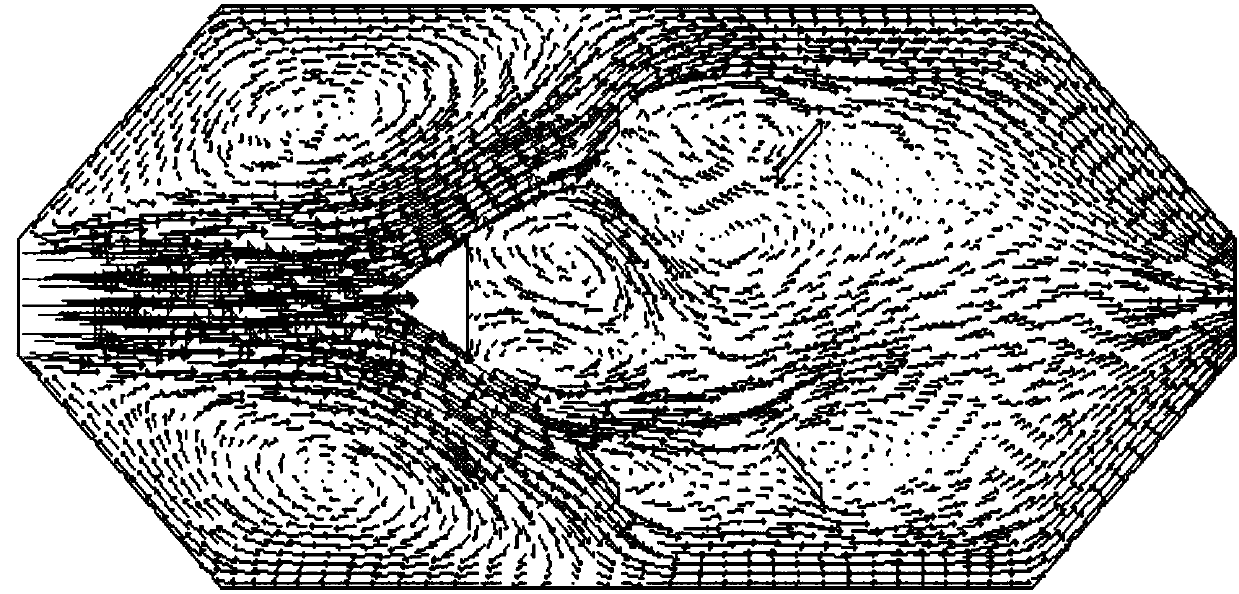
[0039] In this embodiment, the flue gas from the turbulent agglomeration chamber is an axisymmetric hexagonal structure, the entrance is in a sudden expansion shape, and the exit is in a zoom shape. The included angle of the center line of the incoming smoke is 45°. Triangular prism spoiler columns 3 and four vortex sheets 2 are arranged inside the reunion chamber. Every two vortex sheets form a group, and the incoming smoke is arranged axisymmetrically. The included angle between the vortex sheet 2 and the center line of the incoming smoke is 45°, and the shortest distance between the vortex sheet 2 and the wall of the reunion chamber is 0.18 of the total width of the reunion chamber; the front view shape of the triangular prism spoiler column 3 is equal to The base of the isosceles triangle is perpendicular to the center line of the incoming smoke, the apex of the isosceles triangle faces the entrance and is located on the center line of the incoming smoke, and the distance b...


PUM


Abstract

The invention relates to a turbulence agglomeration chamber and a method for removing ultrafine particles applying the same. The turbulence agglomeration chamber is characterized in that the agglomeration chamber is of a symmetrical hexagonal structure taking an incoming flow flue gas as the axis, an inlet is in a sudden-expansion state, an outlet is in a contracting state, the ratio of the width of the inlet to the total width of the agglomeration chamber is 0.2 to 0.4, the inclined angle of the wall face of the inlet and a center line of the incoming flow flue gas is 30 degrees to 60 degrees, the agglomeration chamber is internally provided with a triangular prism pin fin and 2n vortex sheets, n is larger than or equal to 1, every two vortex sheets form a group and are arranged symmetrically by taking the incoming flow flue gas as the axis, the inclined angle of each vortex sheet and the center line of the incoming flow flue gas is 30 degrees to 60 degrees, and the shortest distance between the vortex sheets and the wall face of the agglomeration chamber is 1 / 6 to 1 / 4 of the total width of the agglomeration chamber; the front view shape of the triangular prism pin fin is an isosceles triangle, the bottom edge of the isosceles triangle is perpendicular to the center line of the incoming flow flue gas, the vertex angle of the isosceles triangle directly faces the inlet and is located on the center line of the incoming flow flue gas, and the distance between the center of the isosceles triangle and the inlet is 1 / 4 to 1 / 3 of the total length of the agglomeration chamber.

Description

technical field [0001] The invention belongs to the technical field of removing ultrafine particles in flue gas of coal-fired boilers, and in particular relates to a turbulent agglomeration chamber and a method for removing ultrafine particles using the agglomeration chamber. Background technique [0002] In recent years, fine particulate matter (referred to as PM 2.5 ) on the air environment and people's health has become the focus of public attention. my country is the country with the largest coal consumption in the world, especially the coal consumption in coal-fired boilers is huge. Therefore, soot particles produced by coal combustion have become one of the main sources of atmospheric particles. Frequent smog weather has seriously affected people's daily life. After dusty air is inhaled into the human body, it will cause related respiratory diseases and affect human health. At the same time, the emission of soot particles also causes the decline of air quality, leadi...

Claims


Application Information

Patent Timeline
Patent Type & Authority Patents(China)
IPC IPC(8): B01D51/02
CPCB01D51/02
Inventor 陈占秀李阳杨历刘联胜闵春华李想
Owner HEBEI UNIV OF TECH
Why Eureka
Try Eureka