Uplink carrier aggregation control method, device and terminal equipment

A technology of carrier aggregation and terminal equipment, applied in advanced technology, power management, electrical components, etc., can solve problems such as power consumption differences and differences, and achieve the effect of balancing user experience, ensuring battery life, and reasonably controlling power consumption

Active Publication Date: 2017-11-24
GUANGDONG OPPO MOBILE TELECOMM CORP LTD
View PDF3 Cites 0 Cited by
  • Summary
  • Abstract
  • Description
  • Claims
  • Application Information

AI Technical Summary

Problems solved by technology

[0003] In the above-mentioned carrier aggregation technology, the carrier is divided into uplink carrier and downlink carrier. Due to the influence of the working mode and structure of the terminal equipment, the impact of the downlink carrier on the power consumption of the terminal equipment is not large; while the aggregation of uplink carriers, especially in different frequency bands The aggregation between multiple RF transmission paths requires simultaneous transmission. Since the RF transmission path, especially the RF power amplifier in it, is a high-power device, the uplink carrier has a higher power consumption than terminal equipment without carrier aggregation. Significant differences
That is, the power consumption of an uplink carrier aggregation terminal device will vary significantly with the strength of the terminal device signal and the registered frequency band. If the uplink carrier works in a frequency band with weak signal or high power consumption of the terminal device itself, it may Sacrifice the battery life of the terminal equipment in exchange for the data experience of the current terminal equipment

Method used


Image

  • Uplink carrier aggregation control method, device and terminal equipment
  • Uplink carrier aggregation control method, device and terminal equipment
  • Uplink carrier aggregation control method, device and terminal equipment

Examples


Embodiment Construction

[0028] Embodiments of the present invention are described in detail below, examples of which are shown in the drawings, wherein the same or similar reference numerals designate the same or similar elements or elements having the same or similar functions throughout. The embodiments described below by referring to the figures are exemplary and are intended to explain the present invention and should not be construed as limiting the present invention.

[0029] The method, device and terminal equipment for controlling uplink carrier aggregation according to the embodiments of the present invention are described below with reference to the accompanying drawings. It should be noted that the terminal device in the embodiment of the present invention may be a mobile phone, a tablet computer, a personal digital assistant, a wearable device, and other hardware devices that have various operating systems and can be connected to a communication network.

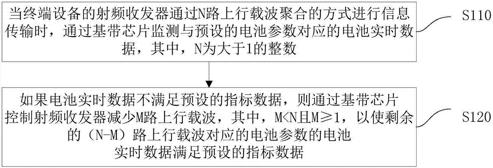
[0030] figure 1 It is a flowcha...


PUM


Abstract

The invention discloses an uplink carrier aggregation control method and device and terminal equipment. The method comprises the following steps: monitoring battery real-time data corresponding to preset battery parameters through a baseband chip when a radio-frequency transceiver of the terminal equipment performs information transmission in an N-path uplink carrier aggregation way, wherein N is an integer being greater than 1; and controlling the radio-frequency transceiver to reduce M paths of uplink carriers through the baseband chip if the battery real-time data do not satisfy preset index data, wherein M is smaller than N, and greater than or equal to 1 in order that the battery real-time data of the battery parameters corresponding to the rest of (N-M) paths of uplink carriers satisfy the preset index data. According to the method, the battery real-time data corresponding to the battery parameters of the terminal equipment are monitored, and the number of paths of the uplink carriers is reduced when the battery real-time data do not satisfy the preset index data, so that power consumption of the terminal equipment is controlled reasonably, and the user experience is balanced on the premise of ensuring the cruising ability of the terminal equipment.

Description

technical field [0001] The present invention relates to the technical field of terminal equipment manufacturing, in particular to an uplink carrier aggregation control method, device and terminal equipment. Background technique [0002] With the development of communication technology, especially the development of 4G technology, various technologies to improve the operating speed of LTE network have emerged as the times require. In the prior art, the carrier aggregation technology can be used to improve the operating rate of the LTE network of the terminal equipment by increasing the transmission bandwidth of the system. [0003] In the above-mentioned carrier aggregation technology, the carrier is divided into uplink carrier and downlink carrier. Due to the influence of the working mode and structure of the terminal equipment, the impact of the downlink carrier on the power consumption of the terminal equipment is not large; while the aggregation of uplink carriers, especi...

Claims


Application Information

Patent Timeline
Patent Type & Authority Patents(China)
IPC IPC(8): H04W52/02H04B1/40
CPCH04B1/401H04W52/0277H04W52/028Y02D30/70
Inventor 伏奎
Owner GUANGDONG OPPO MOBILE TELECOMM CORP LTD
Why Eureka
Try Eureka