
A local time synchronization system and monitoring method thereof

A time synchronization system and local area technology, applied in the field of communication, can solve the problems of scattered distribution, high cost, and large number of sub-clocks, and achieve the effects of saving manpower and cost, reducing hardware requirements, and reducing hardware costs

Active Publication Date: 2019-07-09
FIYTA HOLDINGS LTD
View PDF7 Cites 0 Cited by
  • Summary
  • Abstract
  • Description
  • Claims
  • Application Information

AI Technical Summary

Problems solved by technology

During manual monitoring, the monitoring personnel must stay within the installation range of the entire system during working hours, and keep going to and from each sub-clock to monitor the operating status of the sub-clocks, and then report to the police and deal with any abnormalities. However, for airports, stations, For large-scale complex buildings, the number of sub-clocks in the local time synchronization system is large and the distribution is scattered. Manual monitoring not only cannot find abnormal points in a timely and effective manner, but also greatly increases the workload of monitoring personnel; It requires a computer to connect to the main control system of the local time synchronization system, and use specially developed software to monitor the sub-clocks in the system. The cost is high. At the same time, it is necessary to add staff to check the monitoring status, which may also cause delays. abnormal situation found

Method used


Image

  • A local time synchronization system and monitoring method thereof
  • A local time synchronization system and monitoring method thereof
  • A local time synchronization system and monitoring method thereof

Examples


Embodiment Construction

[0031] In order to make the object, technical solution and advantages of the present invention clearer, the present invention will be further described in detail below in conjunction with the accompanying drawings and embodiments. It should be understood that the specific embodiments described here are only used to explain the present invention, not to limit the present invention.

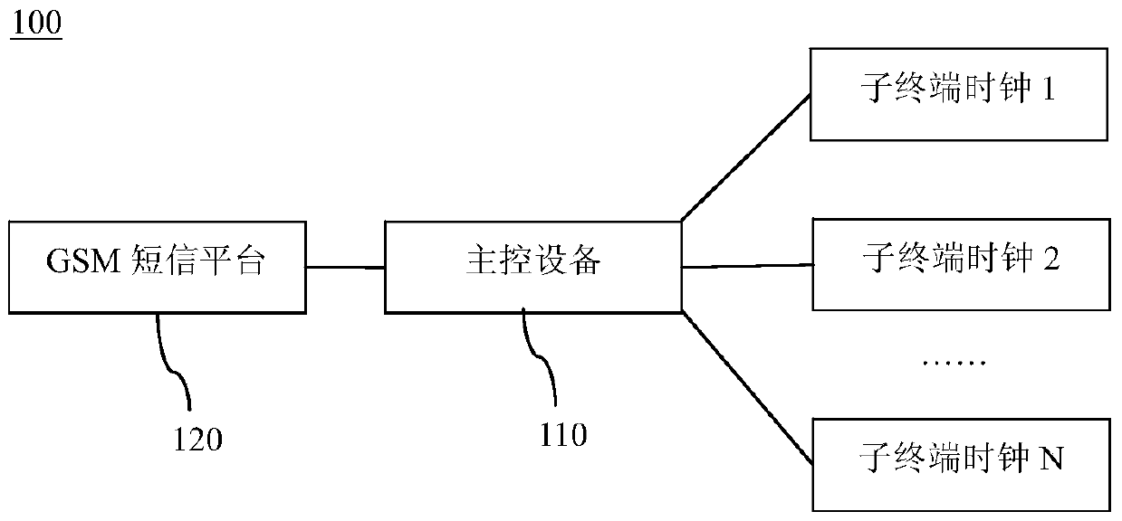
[0032] like figure 1 Shown is a schematic structural diagram of a local time synchronization system in a preferred embodiment of the present invention. refer to figure 1 , the system 100 includes a main control device 110 and N sub-terminal clocks, where N is a positive integer greater than 1, and each sub-terminal clock is connected to the main control device 110, specifically, in this embodiment, the main control device 110 A plurality of parallel ports (not shown in the figure) are arranged on it, and each sub-terminal clock is correspondingly connected to the parallel port of the main control...


PUM


Abstract

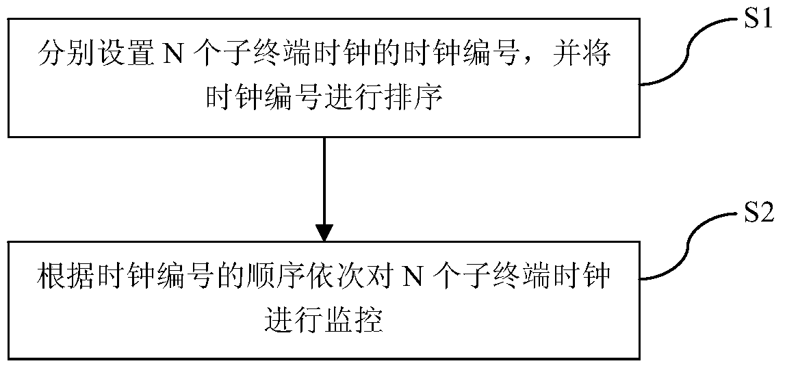
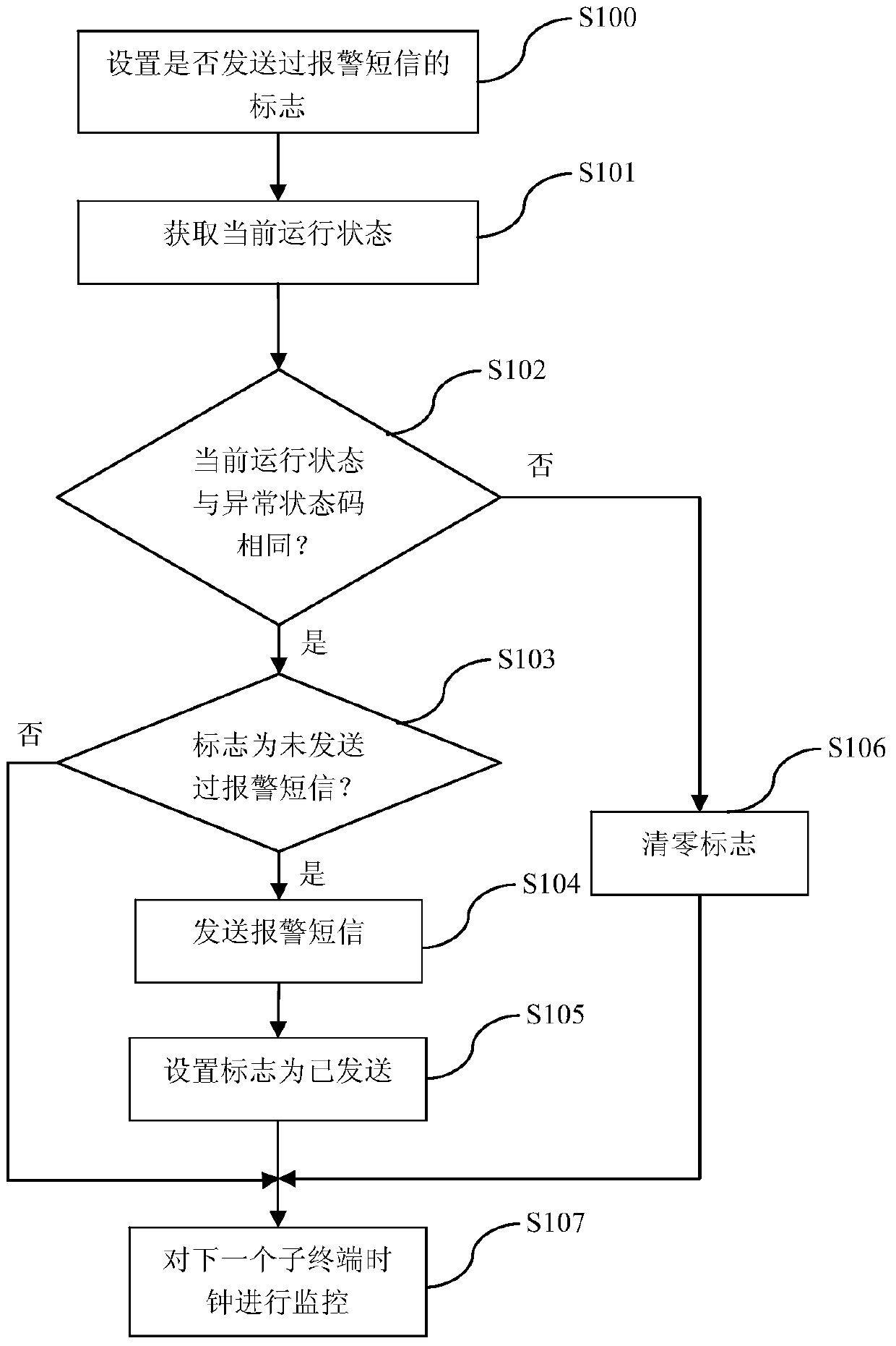
The invention provides a local area time synchronization system. The system includes a main control device and N sub terminal clocks, wherein N is a positive integer greater than 1, each sub terminal clock is connected with the main control device, and the main control device sets the clock serial numbers of the N sub terminal clocks, ranks the clock serial numbers, and monitors the N sub terminal clocks according to the sequence of the clock serial numbers sequentially. The invention also provides a monitoring method of the system. With the local area time synchronization system and the monitoring method thereof of the invention adopted, automatic monitoring can be carried out, the anomalous points of the terminal clocks can be timely detected, an alarm can be given automatically, and therefore, existing manual control and upper computer manual monitoring can be replaced; unattended management can be realized; and a lot of manpower and cost can be saved. The local area time synchronization system and the monitoring method thereof are particularly suitable for being used in airports, railway stations and large-scale integrated constructions. The main control device sets markers of the sub terminal clocks, wherein the markers indicate whether the sub terminal clocks have sent alarm messages, and therefore, a situation that an alarm message is sent repeatedly can be avoided.

Description

technical field [0001] The present invention relates to the technical field of communication, and more specifically, to a local area time synchronization system and a monitoring method thereof. Background technique [0002] With the development of society and the rapid development of urban construction, more and more airports, stations, and large buildings are put into use, and the demand for local multi-terminal clock systems is also growing rapidly. The existing local area time synchronization system is to transmit the standard time signal to each terminal clock in the system (hereinafter referred to as "secondary clock"), and each terminal clock calibrates the local time after receiving the time correction signal, so as to realize each terminal clock in the system. Synchronization of the indicated time of the terminal clock. [0003] At present, the existing local area time synchronization system mainly relies on manual monitoring and upper computer software monitoring t...

Claims


Application Information

Patent Timeline
Patent Type & Authority Patents(China)
IPC IPC(8): H04L12/24H04J3/06
CPCH04J3/0638H04L41/06
Inventor 屈哲王文晓曾庆宇巫玲坚鲍贤勇
Owner FIYTA HOLDINGS LTD
Learn More