Handle-type high-voltage connector

A high-voltage connector and handle technology, applied in the direction of vehicle connector, connection, two-part connection device, etc., can solve the problems of scrap, easy to break or damage, inconvenient to use, etc., so as to reduce maintenance costs and avoid easily damaged parts. Effect

Active Publication Date: 2016-08-10
SCED ELECTRONICS CO LTD
View PDF7 Cites 12 Cited by
  • Summary
  • Abstract
  • Description
  • Claims
  • Application Information

AI Technical Summary

Problems solved by technology

However, in the case of high-voltage connections, the size and weight of the high-voltage plug and high-voltage socket itself are relatively large, so the handle mechanism requires a large external force to rotate to achieve the locking and separation of the high-voltage connector
However, since the space at the handle connecting rod is very limited, as disclosed in the above-mentioned prior art, the secondary locking mechanism of the handle with a buckle / slot structure and its ejection device are adopted, so the operator is very laborious and laborious to operate. inconvenient to use
In addition, the buckle / slot structure is also prone to engagement failure due to vibration, etc. Although the ejection device is further provided in the above-mentioned prior art, in the actual working environment of the high-voltage connector, the ejection device It is also easy to loosen due to vibration etc.
Not only that, such a buckle / slot structure is difficult to withstand excessive external force due to the relatively concentrated force, so when the operator exerts too much force, it may also cause other safety hazards due to the sudden damage or separation of the buckle and the slot. Hidden danger
In addition, if the buckle / slot structure is often scrapped due to excessive external force during use, it is necessary to frequently replace the handle or some components of the advanced connector
Furthermore, since the chute and the slide block of the ejection device are also relatively thin in structure, they are easily broken or damaged during frequent use, resulting in the scrapping of the entire handle and high maintenance costs

Method used


Image

  • Handle-type high-voltage connector
  • Handle-type high-voltage connector
  • Handle-type high-voltage connector

Examples


Embodiment Construction

[0027] In the following, the technical content, structural features and achieved technical objectives and technical effects of the preferred embodiments of the present invention will be described in detail with reference to the accompanying drawings.

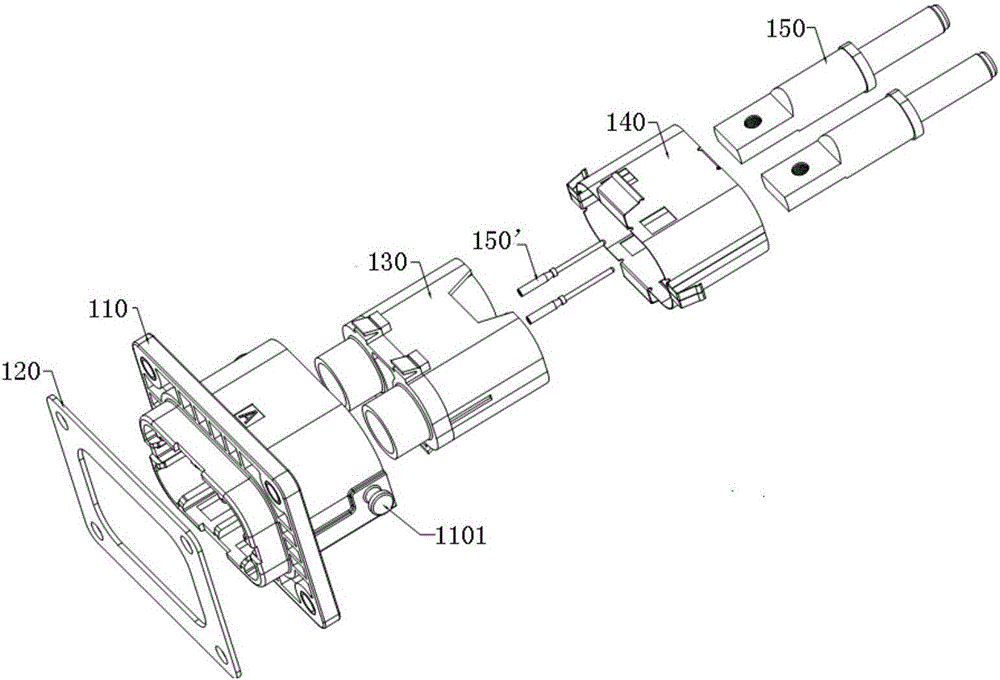
[0028] The handle-type high-voltage connector of the present invention is composed of a high-voltage socket 100 and a high-voltage plug 200 . First, if figure 1 As shown, the high-voltage socket 100 includes: a socket shell 110, a waterproof ring 120, a socket rubber core assembly 130, a socket shield 140, and power pins 150 and signal pins 150'. The socket rubber assembly 130 is located in the socket housing 110, the socket shielding cover 140 is arranged between the socket rubber assembly 130 and the socket housing 110, and the socket shielding cover 140 fully covers the socket rubber assembly 130; There are two through holes, and the two power pins 150 are inserted into the two through holes of the socket rubber core assemb...


PUM


Abstract

The invention discloses a handle anti-loosening mechanism, which is easy to operate, long in service life and reliable in secondary locking, and a handle-type high-voltage connector using the handle anti-loosening mechanism. The handle anti-loosening mechanism comprises a main body slide groove arranged on a high-voltage connector main body in an integrated manner; a locking block detachably and slidably arranged in the main body slide groove to limit or allow a handle of the high-voltage connector to rotate with respect to the high-voltage connector main body; and a locking press block detachably arranged on a connecting rod portion of the handle, wherein the locking block has a buckle position for buckling with the main body slide groove, and the locking press block has an abutting portion abutted against the buckle position to allow the locking block to slide in the main body slide groove.

Description

technical field [0001] The present invention relates to a handle-type high-voltage connector for connecting high-voltage cables, and more specifically to a handle-type high-voltage connector with a handle-type high-voltage connector and a handle-type high-voltage connector with the handle-type high-voltage connector. Background technique [0002] In recent years, significant progress has been made in high-voltage connector technology. For example, in eco-friendly vehicles such as hybrid vehicles and electric vehicles, high-voltage connectors for connecting high-voltage cables are widely used. In order to make the two connector parts (male side connector part and female side connector part) of the high voltage plug and the high voltage socket easy to lock and separate so that they are in the mated state and the non-fitted state, in the high voltage connector A handle part is often added, and such a high-voltage connector is called a handle-type high-voltage connector. [000...

Claims


Application Information

Patent Timeline
IPC IPC(8): H01R13/629H01R13/639H01R24/00
CPCH01R13/629H01R13/639H01R24/00H01R2201/26
Inventor 王南
Owner SCED ELECTRONICS CO LTD
Why Eureka
Try Eureka