
A device and method for comprehensive utilization of solar energy based on solar optical fiber

A technology of solar energy and optical fiber, applied in the field of comprehensive solar energy utilization devices based on solar optical fibers, can solve the problems of not considering the utilization of solar heat energy, large losses, and inability to automatically adjust, so as to improve comprehensive utilization efficiency, reduce labor costs, and improve accuracy Effect

Active Publication Date: 2019-03-01
CHINA AEROSPACE CONSTR GROUP
View PDF11 Cites 0 Cited by
  • Summary
  • Abstract
  • Description
  • Claims
  • Application Information

AI Technical Summary

Problems solved by technology

[0006] In the existing patents related to solar fiber optic light guide lighting, there are various disadvantages, such as patent 201020621250.4, when the sunlight cannot be directly irradiated, the lighting effect will be very poor, and the utilization of solar heat energy is not considered at the same time ; Patents 200920277492.3 and 201220708663.5 do not consider the comprehensive utilization of solar energy, and cannot get rid of the consumption of traditional energy; After that, it cannot be automatically adjusted, etc., and the direction of the tracking device needs to be adjusted manually on a regular basis
Patent 201320638567.2 is to convert solar energy into electrical energy and then perform lighting, so that the loss of light energy utilization is relatively large, and the solar panel is not completely perpendicular to the sunlight, and the efficiency of light energy generation is low
Patent 201510187982.4 does not consider the thermal energy utilization of solar energy

Method used


Image

  • A device and method for comprehensive utilization of solar energy based on solar optical fiber
  • A device and method for comprehensive utilization of solar energy based on solar optical fiber
  • A device and method for comprehensive utilization of solar energy based on solar optical fiber

Examples


Embodiment Construction

[0038] In order to describe the technical solution of the present invention in more detail, the technical solution of the present invention will now be described in detail in conjunction with the accompanying drawings, specifically as follows:

[0039] A solar energy comprehensive utilization device based on solar optical fiber includes a solar energy comprehensive collector system, a power generation system, a lighting system, a thermal energy supply system and a control system;

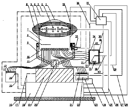
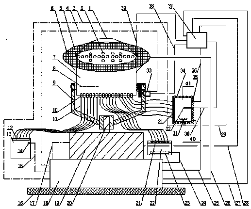
[0040] The solar energy comprehensive utilization device is installed on the roof or other open areas, and can make full use of sunlight energy. The integrated collector 7 is an important device for utilizing sunlight, and is composed of a transparent ultraviolet filter protective cover 1, a Fresnel lens 2, a heat-insulating quartz and infrared filter assembly 8, a heat-resistant quartz coupler 10, and an optical fiber 11. The transparent ultraviolet filter protective cover 1 is installed on the top...


PUM


Abstract

A comprehensive solar energy utilization device based on solar optical fiber includes a comprehensive solar collector system, a power generation system, a lighting system, a thermal energy supply system and a control system; by using the heat-resistant quartz coupler and optical fiber of the comprehensive solar collector system to pair the Fresnel lens The obtained solar energy is divided and utilized, and connected to the lighting system, power generation system and thermal energy supply system respectively, and passed through Set the distance between the specific heat-resistant quartz coupler and the Fresnel lens and the end area of ​​the heat-resistant quartz coupler to maximize the utilization of light energy; use the solar fiber light guide lighting system to evenly introduce clean and healthy sunlight into the room , providing people with a comfortable and healthy lighting environment, and at the same time solving some areas that require all-weather lighting, replacing electric lighting during the day, and greatly saving electricity bills. Moreover, solar power generation and thermal energy utilization are comprehensively considered to improve the comprehensive utilization efficiency of solar energy and reduce the consumption of traditional energy.

Description

technical field [0001] The invention relates to the field of comprehensive utilization of solar energy, in particular to a device and method for comprehensive utilization of solar energy based on solar optical fibers. Background technique [0002] With the rapid development of my country's economy and the increasingly serious problems of energy shortage and environmental pollution, energy conservation, emission reduction and low-carbon life have become the development trend of all walks of life. my country is rich in solar energy resources, and the total annual solar radiation of more than two-thirds of the country's land area exceeds 5.0 GJ / m 2 , the annual average sunshine hours are more than 2200 hours. Especially in the vast North China and Northwest China, there is sufficient sunshine, which provides good natural conditions for the development and utilization of solar energy. [0003] As urban buildings tend to be high-rise and dense, only relying on traditional light...

Claims


Application Information

Patent Timeline
Patent Type & Authority Patents(China)
IPC IPC(8): F21S19/00F21V5/04F21V5/08F21V9/06F24S20/40F24S23/30F24S50/00H02S10/00H02S40/22H02S40/38F21Y115/10
CPCF21S19/005F21V5/04F21V5/08F21V9/06F24S20/40F24S23/31F24S50/40H02S10/00H02S40/22H02S40/38Y02E10/40Y02E10/52Y02E70/30
Inventor 梁普吴燕李淑玉
Owner CHINA AEROSPACE CONSTR GROUP
Learn More