Automatic clutch device with free stroke and rotating door mechanism

An automatic clutch, revolving door technology, applied in the direction of the power control mechanism, the control mechanism of the wing fan, the clutch, etc., can solve the problems of the complex structure of the electromagnetic clutch, affect the quality of use, and high production costs, and achieve simple structure, convenient production, and torque. Deliver good results

Active Publication Date: 2016-08-10
SHANGHAI HUAMING INTELLIGENT TERMINAL EQUIP
View PDF4 Cites 2 Cited by
  • Summary
  • Abstract
  • Description
  • Claims
  • Application Information

AI Technical Summary

Problems solved by technology

[0002] In the field of mechanical applications, for some shaft mechanisms that require free travel, at present, electromagnetic clutches are combined with controllers to control the torque transmission between shafts and shafts. The structure of electromagnetic clutches is relatively complicated, and the production cost is relatively high. At the same time, the control system is added, the whole system is more complicated and the cost is high, and if a simple missing block structure is used for torque transmission, due to the large driving force when the shaft is rotating, the missing blocks on the two shafts will be in contact. At the moment, it will generate a lot of noise and vibration at the same time, which will affect the quality of use

Method used


Image

  • Automatic clutch device with free stroke and rotating door mechanism
  • Automatic clutch device with free stroke and rotating door mechanism
  • Automatic clutch device with free stroke and rotating door mechanism

Examples


Embodiment Construction

[0023] The following will clearly and completely describe the technical solutions in the embodiments of the present invention with reference to the accompanying drawings in the embodiments of the present invention. Obviously, the described embodiments are only some, not all, embodiments of the present invention. Based on the embodiments of the present invention, all other embodiments obtained by persons of ordinary skill in the art without creative efforts fall within the protection scope of the present invention.

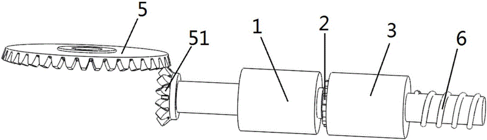
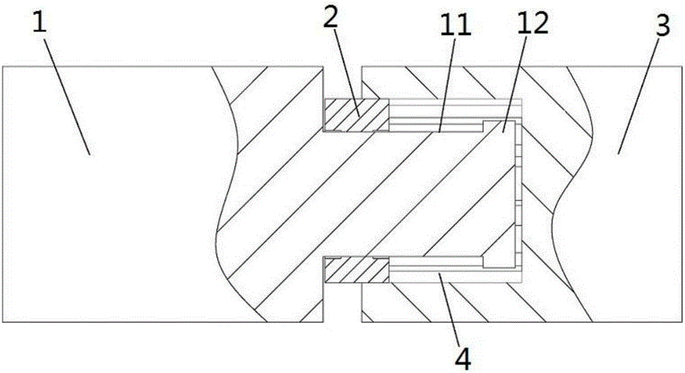
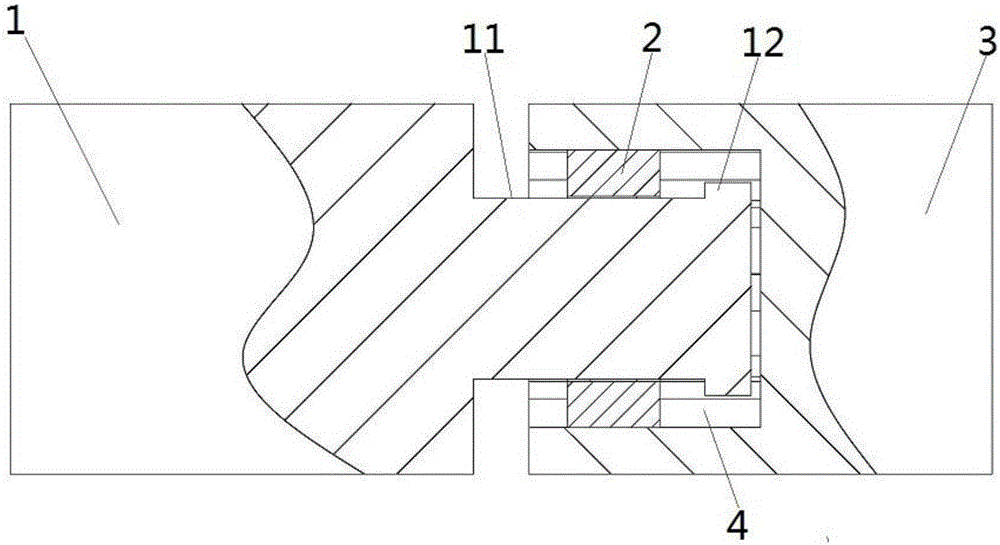
[0024] Such as Figure 1 to Figure 6 As shown, a kind of automatic clutch device with free stroke of the present invention comprises a first drive shaft 1, a clutch drive member 2, and a second drive shaft 3, and the first drive shaft 1 passes through the clutch drive assembly It is connected with the second drive shaft 3 in transmission. In this embodiment, the first drive shaft 1 is a stepped shaft. The surface of the small end shaft of the first drive shaft 1 is...


PUM


Abstract

The invention provides an automatic clutch device with the free stroke. The automatic clutch device comprises a first drive shaft, a clutch drive part and a second drive shaft; the first drive shaft is in drive connection with the second drive shaft through a clutch drive component, the first drive shaft is a ladder shaft, threads are arranged on the surface of a small end shaft of the first drive shaft, and the clutch drive component is rotatably arranged on the threads; a baffle used for blocking the clutch drive component is arranged on the end face of the small end of the first drive shaft, a counter bore is formed in the end face of one end of the second drive shaft, and the small end of the first drive shaft, the clutch drive component and the baffle are all embedded in the counter bore; the clutch drive component and the second drive shaft are connected in a torque transmission manner and can slide axially relative to the inner wall of the counter bore; and compared with the prior art, the automatic clutch device is simple in structure, reasonable in design, convenient to manufacture, reliable in torque transmission, wide in application range and high in practicability, and the cost is reduced.

Description

technical field [0001] The invention relates to the technical field of clutch transmission equipment, in particular to an automatic clutch device with free travel and a revolving door mechanism using the clutch device. Background technique [0002] In the field of mechanical applications, for some shaft mechanisms that require free travel, at present, electromagnetic clutches are combined with controllers to control the torque transmission between shafts and shafts. The structure of electromagnetic clutches is relatively complicated, and the production cost is relatively high. At the same time, the control system is added, the whole system is more complicated and the cost is high, and if a simple missing block structure is used for torque transmission, due to the large driving force when the shaft is rotating, the missing blocks on the two shafts will be in contact. At the moment, there will be a lot of noise and vibration at the same time, which will affect the quality of u...

Claims


Application Information

Patent Timeline
Patent Type & Authority Applications(China)
IPC IPC(8): F16D41/02E05F15/00
CPCE05F15/00F16D41/02
Inventor 张亮徐剑峰王鑫顾起英
Owner SHANGHAI HUAMING INTELLIGENT TERMINAL EQUIP
Why Eureka
Try Eureka