
Hydraulic impactor

A technology of hydraulic impactor and impact body, which is applied to the drilling driving device, drilling equipment, earthwork drilling and other directions in the wellbore, can solve the problems of cumbersome impact process, insufficient impact force of impactor, low efficiency, etc. Sensitivity, shock effect, long life effect

Active Publication Date: 2016-08-10
NORTHEAST GASOLINEEUM UNIV
View PDF7 Cites 4 Cited by
  • Summary
  • Abstract
  • Description
  • Claims
  • Application Information

AI Technical Summary

Problems solved by technology

[0003] The purpose of the present invention is to provide a hydraulic impactor, which is used to solve the problems of insufficient impact force, low efficiency and cumbersome impact process of existing impactors.

Method used


Image

  • Hydraulic impactor
  • Hydraulic impactor
  • Hydraulic impactor

Examples


Embodiment Construction

[0023] Below in conjunction with accompanying drawing, the present invention will be further described:

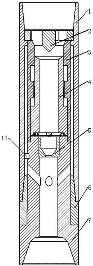
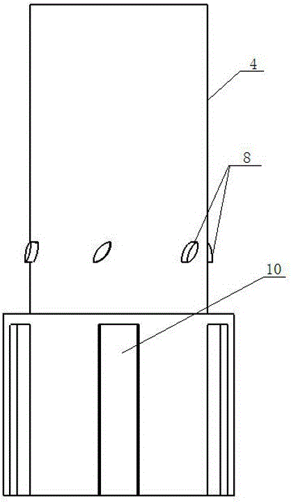
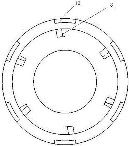
[0024] Such as figure 1 As shown, this hydraulic impactor includes a body 1, a resistance booster 2, a pressure isolation cylinder 3, an impact body 4, and an anvil 7. The body 1 is a hollow cylinder, the drag booster 2 is fixed on the upper part of the body 1, and the anvil The sub 7 is fixed on the lower part of the body 1, the anvil 7 extends into the body 1, the pressure isolation cylinder 3 is between the anvil 7 and the resistance booster 2, and the lower end of the pressure isolation cylinder 3 is engaged with the upper end of the anvil 7; the anvil Nozzle 5 is fixed inside 7, the impact body 4 is arranged in the pressure isolation cylinder 3, the outer wall of the impact body 4 is matched with the inner wall of the pressure isolation cylinder 3, the lower end surface of the impact body 4 is matched with the upper end surface of the anvil 7, so that the impact body ...


PUM


Abstract

The invention relates to a hydraulic impactor. The hydraulic impactor comprises a body, a drag device, a pressure isolation barrel, an impact body and an anvil, wherein the body is a hollow cylinder, the drag device is fixed at the upper part of the body, the anvil is fixed at the lower part of the body and extends into the body, the pressure isolation barrel is arranged between the anvil and the drag device, and the lower end of the pressure isolation barrel is meshed with the upper end of the anvil; the impact body is communicated with an inner cavity of the anvil, a nozzle is fixed in the anvil, the impact body is arranged in the pressure isolation barrel, the outer wall of the impact body is matched with the inner wall of the pressure isolation barrel, the lower end surface of the impact body is matched with the upper end surface of the anvil, and the impact body is restrained to perform reciprocating motion; a downward bulge is arranged in the center of the drag device and adopts a cylinder and cone combined body, the impact body is a barrel-shaped body provided with a step outside, and the bulge of the drag device corresponds to an upper end port of the impact body. Hydraulic energy is used sufficiently, a drill bit is enabled to generate axial vibration during rotation work, and the rock breaking efficiency is increased.

Description

technical field [0001] The invention relates to a drilling tool in the petroleum industry, in particular to a high-efficiency rock-breaking and speed-increasing tool suitable for medium-hard to hard formations, in particular to a hydraulic impactor. Background technique [0002] With the development of the petroleum industry, my country's demand and requirements for petroleum resources are getting higher and higher. The exploration and development of petroleum continues to expand, the depth of oil production wells continues to deepen, and the drilling environment is becoming more and more complex. The power loss of traditional drilling equipment The drilling speed is relatively large, the drilling speed is slow, and the tools are easily damaged due to their own conditions, which leads to long drilling time and high drilling costs, which seriously restrict the development process of oil and gas fields. Therefore, developing new tools has become a new trend. In order to meet t...

Claims


Application Information

Patent Timeline
IPC IPC(8): E21B4/06
CPCE21B4/06
Inventor 李玮纪照生徐彤鑫皮彦夫刘丽孙文峰
Owner NORTHEAST GASOLINEEUM UNIV
Learn More