
Induction hardening fixture for inner cavity of three-pillar groove shell of flange plate

A technology of induction hardening and three-column grooved shell, which is applied in the field of clamping fixtures, can solve the problems of inconvenient clamping, large clamping range of product differences, etc., to ensure effective clamping, expand the clamping range, and eliminate gaps Effect

Inactive Publication Date: 2016-08-10
芜湖佳先传动轴有限公司
View PDF0 Cites 0 Cited by
  • Summary
  • Abstract
  • Description
  • Claims
  • Application Information

AI Technical Summary

Problems solved by technology

[0003] The purpose of the present invention is to overcome the inconvenience of clamping in the induction quenching of the existing flange-type three-column groove shell cavity, and it is necessary to adjust the hydraulic claws of the machine tool manipulator, but the clamping range stroke of the hydraulic claws can only reach 4 mm, which cannot meet the requirements. For the complex situation of large product differences and large clamping range, a kind of induction hardening fixture for the inner cavity of the three-column groove shell of the flange is provided, and the method of clamping the product with a handle clamp on the three-column groove shell of the flange is effectively changed. Lanpan products are ordinary products to avoid the need to adjust the hydraulic claws, effectively expand the use of the machine tool, reduce the adjustment range and time of the machine tool, and improve production efficiency; at the same time, because the locking hook can only rotate around the rotating pin axis, And due to the existence of the rubber elastic body, the product can be quickly clamped and positioned

Method used


Image

  • Induction hardening fixture for inner cavity of three-pillar groove shell of flange plate
  • Induction hardening fixture for inner cavity of three-pillar groove shell of flange plate

Examples


Embodiment Construction

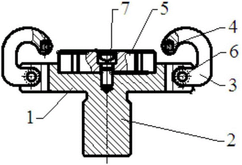
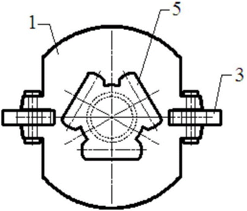
[0019] see figure 1 , 2 , a flange plate three-column groove shell cavity induction hardening fixture, including a base 1, the bottom of the base 1 has an integrally connected connecting handle 2, the two sides of the base 1 are respectively rotated and installed with locking hooks 3, The front ends of the locking hooks 3 are respectively connected with rubber elastic bodies 4, and a positioning block 5 is fixedly installed on the base 1, and the shape of the positioning block 5 is consistent with the inner cavity shape of the three-column groove shell of the flange.

[0020] In the present invention, the connecting handle 2 can be connected with the hydraulic chuck of the induction hardening machine tool.

[0021] The locking hooks 3 are respectively rotatably mounted on both sides of the base 1 through the rotating shaft pins 6 .

[0022] The positioning block 5 is fixed on the base 1 by screws 7 .


PUM


Abstract

The invention discloses an induction quenching fixture for the inner cavity of a three-column groove shell with a flange, which includes a base, the bottom of which is provided with an integrally connected connecting handle, and locking hooks are respectively installed on both sides of the base for locking. The front ends of the hooks are respectively connected with rubber elastic bodies, and a positioning block is fixedly installed on the base, and the shape of the positioning block is consistent with the inner cavity shape of the three-column groove shell of the flange. The connecting handle at the bottom of the base of the present invention can be connected with the hydraulic chuck of the machine tool. At the same time, the locking hook and the rubber elastic body on the locking hook can firmly connect the product to the base after pressing the end face of the flange. The positioning block can locate the position of the product, the base, and the sensor, ensuring the positional relationship between the inner cavity of the product and the sensor, ensuring that the gap between the inner cavity side wall and the sensor can achieve the purpose of effective quenching, and avoiding the The frequent adjustment of the hydraulic jaws of the manipulator of the machine tool saves a lot of adjustment time and improves the production efficiency at the same time.

Description

technical field [0001] The invention relates to the field of clamping fixtures used for induction hardening of the inner cavity sliding ballway of the three-column groove shell of the flange plate sliding constant velocity universal joint at the differential end of the drive shaft of the constant velocity universal joint for automobiles. Specifically, it is an induction hardening fixture for the inner cavity of a three-column groove shell with a flange. Background technique [0002] The universal joint at the differential end of the constant velocity universal joint drive shaft assembly for automobiles is a tripod type constant velocity universal joint that can rotate and slide axially at the same time. There are many forms of connection between the housing of this tripod type sliding constant velocity universal joint and the differential, and the bolt connection through the flange and the bolt holes on the flange is one of them. For the quenching of the inner cavity of the...

Claims


Application Information

Patent Timeline
Patent Type & Authority Applications(China)
IPC IPC(8): C21D1/62
CPCC21D1/62
Inventor 吴望才谢恒新
Owner 芜湖佳先传动轴有限公司
Learn More