Apparatus and method for detecting the current damaged state of a machine

A machine and status technology, applied in the direction of machine/structural component testing, instruments, measuring devices, etc., can solve problems such as blade damage, and achieve the effect of avoiding cost-intensive maintenance

Inactive Publication Date: 2016-08-03
SIEMENS ENERGY GLOBAL GMBH & CO KG
View PDF6 Cites 1 Cited by
  • Summary
  • Abstract
  • Description
  • Claims
  • Application Information

AI Technical Summary

Problems solved by technology

The specific problem here is that at first only a small amount of damage on some blades can eventually lead to complete damage during the continued operation of the machine

Method used


Image

  • Apparatus and method for detecting the current damaged state of a machine
  • Apparatus and method for detecting the current damaged state of a machine

Examples


Embodiment Construction

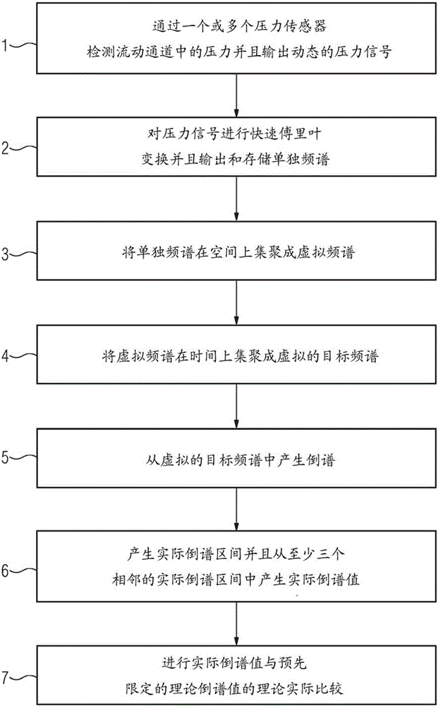
[0040] figure 1The method is shown schematically. In this case, suitable pressure sensors for detecting the current damage state are provided in the machine. At this point, without loss of generality, a compressor is considered below as a machine. In compressors, in particular in axial compressors of gas turbines, dynamic pressure sensors are arranged in the flow channels. Here, the placement of the pressure sensor depends on the desired detection sensitivity. Advantageously, a plurality of such pressure sensors, ie measuring points, are arranged at the outlet of the compressor with the same ordinate at the circumference. This is used for plausibility testing, usability improvement and averaging of detected flow parameters on circumferential coordinates. It is advantageous if the pressure sensor is not arranged in the wall region directly swept away by the rotor blade. This may cause high pressure amplitudes which may interfere with the intended analysis. It may even be ...


PUM


Abstract

A method and apparatus for detecting the current damaged state of a machine is provided. The invention relates to an apparatus for detecting the current damaged state of a machine according to the preamble of claim 1, wherein the data capture and editing device: -comprises a Fast Fourier analysis apparatus, for performing a transformation from pressure signals that are available in the time domain to a frequency domain as discrete-time frequency spectra (2), -additionally comprises a spatial aggregation unit and a temporal aggregation unit that combines the discrete-time frequency spectra, -additionally comprises a cepstrum analysis unit, for producing a cepstrum with various actual cepstrum values from the temporally and spatially aggregated discrete frequency spectra (5), -additionally comprises a computation unit that takes the cepstra produced in this manner and produces, at a previously defined interval of time, a plurality of actual cepstrum intervals comprising adjacent actual cepstrum values, as a result of which an actual cepstrum value, which can be ascertained from at least three adjacent actual cepstrum intervals, can be produced (6), - comprises a unit that computes (7) a target / actual comparison with the actual cepstrum value produced in this manner and a previously determined target cepstrum value.

Description

technical field [0001] The invention relates to all conventional machines designed as fluid machines, such as turbines, gas turbines, compressors, turbochargers or aeroengines. Background technique [0002] A fluid machine, such as a gas turbine, is characterized in that the fluid machine consists of multistage compressor components and turbine components. In this case, a compressor stage or a turbine stage is formed from a stationary guide blade row and a rotating rotor blade row. The guide blade row and the rotor blade row are formed from a plurality of individual blades. Thus, the entire machine consists of several hundred guide vanes and rotor blades. These blades are subjected to high mechanical, aerodynamic and thermal loads during machine operation. [0003] These loads can cause undesired damage to the blade. The particular problem here is that initially only a small amount of damage to some of the blades eventually leads to complete damage during continued opera...

Claims


Application Information

Patent Timeline
Patent Type & Authority Applications(China)
IPC IPC(8): G05B23/02G01M13/00G01H1/00
CPCG01H1/006G05B23/024G01M7/00G05B19/406G05B19/416G05B2219/37371G05B2219/37399
Inventor 乌韦·普法伊费尔汉斯-格尔德·布鲁梅尔
Owner SIEMENS ENERGY GLOBAL GMBH & CO KG
Why Eureka
Try Eureka