Eureka AIR delivers breakthrough ideas for toughest innovation challenges, trusted by R&D personnel around the world.

A method and device for on-site verification of a high-voltage direct current protection system

A protection system, high-voltage direct current technology, applied in the field of electrical engineering, can solve the problems of technical secrecy, inability to verify to the laboratory, no mention of protection action time or timing verification method, etc., to achieve small safety risks and applicable Large, simple wiring effect

Active Publication Date: 2018-07-10
STATE GRID CORP OF CHINA +2
View PDF7 Cites 0 Cited by
  • Summary
  • Abstract
  • Description
  • Claims
  • Application Information

AI Technical Summary

Problems solved by technology

In the stage of operation and maintenance, there is a lack of a convenient and effective on-site calibration device and method for HVDC protection systems
However, the high-voltage direct current protection cannot be verified for a long time, and there are serious hidden dangers for (ultra) high-voltage direct current transmission projects that have been put into operation, especially those that have been in operation for a long time
[0003] There are few existing on-site verification methods for high-voltage DC protection systems, and there are major technical obstacles in practical applications. For example, the Chinese patent document with application number CN201410194153.4 discloses a DC protection verification method, which ignores the photoelectric The difference between current transformers, zero-flux current transformers and conventional AC electronic current transformers is that the data collected by photoelectric current transformers and zero-flux current transformers for DC protection is digital signals, not secondary Current analog signal, which cannot be simulated with a current generator
Another example is the Chinese patent literature with the application number CN201010284079.7 disclosing a DC protection test device and test method, ignoring the fact that the current photoelectric conversion of photoelectric current transformers mostly uses private protocols, and the technology is confidential, so it is impossible to effectively analyze the optical signal The status quo; none of these calibration devices and methods can be conveniently and effectively applied to the on-site calibration of HVDC protection
In addition, on-site verification cannot be the same as laboratory verification. The DC protection action time is verified through a digital simulation system (such as RTDS). The existing on-site verification methods for high-voltage DC protection systems do not mention the protection action time. or timing verification method, which restricts the practicability of on-site verification method

Method used


Image

  • A method and device for on-site verification of a high-voltage direct current protection system
  • A method and device for on-site verification of a high-voltage direct current protection system

Examples


Embodiment Construction

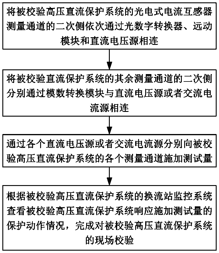
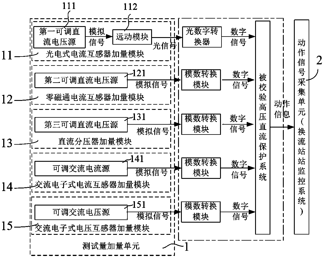
[0041] The following will take the on-site verification work of the verified high-voltage direct current protection system for the pole 1 valve of a ±500kV converter station as an example, to illustrate the on-site verification method and device of the high-voltage direct current protection system of the present invention. The relevant criteria of pole 1 valve DC differential protection only include one photoelectric current transformer measurement channel and one zero-flux current transformer measurement channel. The protection criterion of the pole 1 valve DC differential protection system is divided into two types: alarm and blocking. The alarm criterion is: VDCDP_IVALVE_DIFF > 90A, alarm with a delay of 4s (VDCDP_ALARM); the blocking criterion is VDCDP_IVALVE_DIFF -0.2×IDNC> 1200A, then delay 2ms to switch the system (VDCDP_SS), and then delay 15ms to block DC (VDCDP_TRIP). Among them, VDCDP_IVALVE_DIFF = IDP–IDNC, IDP is the outlet current of the pole bus in the valve hal...


PUM


Abstract

The invention discloses a high voltage direct current protection system field calibration method and device. The method includes the following steps: a secondary side of a photoelectric type current transformer measurement channel of a calibrated high voltage direct current protection system is connected with a direct current voltage source through an optic-digital converter and a telemechanical module in sequence, and secondary sides of the other measurement channels of the calibrated direct current protection system are connected with a direct current voltage source or an alternating current source through analog-to-digital conversion modules; and a test amount is applied to each measurement channel, and according to a protection action situation, field calibration of the calibrated high voltage direct current protection system is completed. The device includes a test amount adding unit and an action signal acquisition unit, wherein the test amount adding unit includes a photoelectric type current transformer amount adding module and a zero-magnetic flux current transformer amount adding module. The high voltage direct current protection system field calibration method and device have the advantages of being easy to implement, having no need to learn a photoelectric type current transformer photoelectric conversion protocol, being low in cost, being small in safety risk and having a wide range of application.

Description

technical field [0001] The invention relates to electrical engineering technology, in particular to an on-site verification method and device for a high-voltage direct current protection system. Background technique [0002] With the deepening demand for long-distance power transmission and regional power grid interconnection, high-voltage direct current transmission technology is widely used in power systems, and (ultra) high-voltage direct current transmission projects have become an indispensable part of large-scale cross-regional power grids. The performance of HVDC transmission largely depends on its control and protection system. As a core equipment high-voltage DC protection system, through DC measuring equipment such as photoelectric current transformers, zero-flux current transformers, and DC voltage dividers, the operating state quantities of high-voltage DC transmission projects are collected to determine whether there are abnormalities or faults, and take measure...

Claims


Application Information

Patent Timeline
Patent Type & Authority Patents(China)
IPC IPC(8): G01R31/00
CPCG01R31/00
Inventor 吴晋波刘海峰许立强康文霍思敏王阳光李振文洪权蔡昱华李大公李理郭思源刘宇陈宏潘伟
Owner STATE GRID CORP OF CHINA
Why Eureka
Eureka Blog
Learn More