
Engine braking method and device for adjusting engine braking power

An engine braking and power technology, applied in the direction of engine control, combustion engine, engine components, etc., can solve problems such as adjusting engine braking power

Active Publication Date: 2021-05-28
MAN TRUCK & BUS AG
View PDF9 Cites 0 Cited by
  • Summary
  • Abstract
  • Description
  • Claims
  • Application Information

AI Technical Summary

Problems solved by technology

[0007] The disadvantage of such engine braking methods is that they require additional bypass elements or modifications of the exhaust turbocharger (variable turbine geometry or variable guide vane cascade)
Also, it is impossible to regulate the engine braking power with the desired accuracy

Method used


Image

  • Engine braking method and device for adjusting engine braking power
  • Engine braking method and device for adjusting engine braking power
  • Engine braking method and device for adjusting engine braking power

Examples


Embodiment Construction

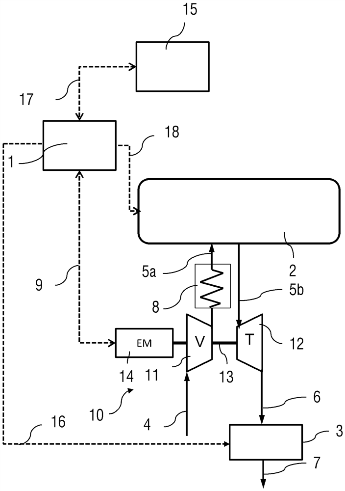
[0048] figure 1 An engine braking device according to an embodiment of the present invention is shown in block diagram form. The engine braking device comprises a supercharged internal combustion engine 2 of a commercial vehicle, and an electric motor-assisted exhaust-gas turbocharger 10 associated therewith, also referred to hereinafter as ETC 10 . The motor-assisted exhaust-gas turbocharger 10 comprises a turbine 12 which is driven by exhaust gas from the internal combustion engine 2 , the exhaust gas being fed to the turbine 12 via the exhaust line 5 b. Thereafter, the exhaust-gas mixture flows via the turbine outlet through the exhaust line 6 , in which the engine brake disk 3 known per se is arranged, the exhaust-gas mixture flows via a further exhaust line 7 to the exhaust port. The turbine 12 is connected to the compressor 11 by a shaft 13 . Fresh air is fed to the compressor 11 via the compressor inlet 4 . The compressor 11 compresses charge air to feed the internal...


PUM


Abstract

The invention relates to an engine braking method and a device for adjusting engine braking power. In particular, the invention relates to an engine braking method for a supercharged internal combustion engine with an exhaust-gas turbocharger. The invention also relates to a device for adjusting the engine braking power of a motor vehicle with a supercharged internal combustion engine. According to the invention, the exhaust-gas turbocharger is an electric motor-assisted exhaust-gas turbocharger, wherein the desired or required engine braking power is set by accelerating the exhaust-gas turbine by operating (S4) the electric motor of the exhaust-gas turbocharger. This is achieved by braking the rotor of the supercharger and / or by braking the rotor (11, 12, 13) by generator operation (S5) of the exhaust-gas turbocharger.

Description

technical field [0001] The invention relates to an engine braking method for a supercharged internal combustion engine with an exhaust-gas turbocharger. The invention also relates to a device for adjusting the engine braking power of a motor vehicle with a supercharged internal combustion engine. Background technique [0002] Equipping motor vehicles, especially commercial vehicles, with engine brakes in the form of engine back pressure brakes (also known as exhaust flap brakes or engine brake discs) is derived from the prior art (eg from German Published Application DE19821130A1 or European Patent Application EP1258603A1 )known. In the case of an engine back pressure brake, the exhaust gases are built up via a throttle valve, which is built in the exhaust line and arranged before or usually after the exhaust-gas turbocharger, wherein the back pressure is built up via the throttle valve in the in the exhaust duct. As it expels cylinder charge, the engine performs addition...

Claims


Application Information

Patent Timeline
Patent Type & Authority Patents(China)
IPC IPC(8): F02D9/06F02D23/00F02B37/10F02B39/00
CPCF02B37/10F02B39/00F02D9/06F02D23/00F02B37/14F02B39/10F02D9/08F02D41/0007F02D41/12F02D41/123Y02T10/12
Inventor A.帕彭黑默A.索默曼
Owner MAN TRUCK & BUS AG
Learn More