
Method for limiting hydraulic brake with the maximum invoked break power

A technology of hydraulic brakes and braking power, applied in the directions of hydraulic brakes, hydraulic resistance brakes, brakes, etc., can solve problems such as limiting the availability of hydraulic brakes

Inactive Publication Date: 2008-02-06
VOITH TURBO GMBH & CO KG
View PDF3 Cites 5 Cited by
  • Summary
  • Abstract
  • Description
  • Claims
  • Application Information

AI Technical Summary

Problems solved by technology

But this undesirably limits the usability of hydraulic brakes

Method used


Image

  • Method for limiting hydraulic brake with the maximum invoked break power
  • Method for limiting hydraulic brake with the maximum invoked break power
  • Method for limiting hydraulic brake with the maximum invoked break power

Examples


Embodiment Construction

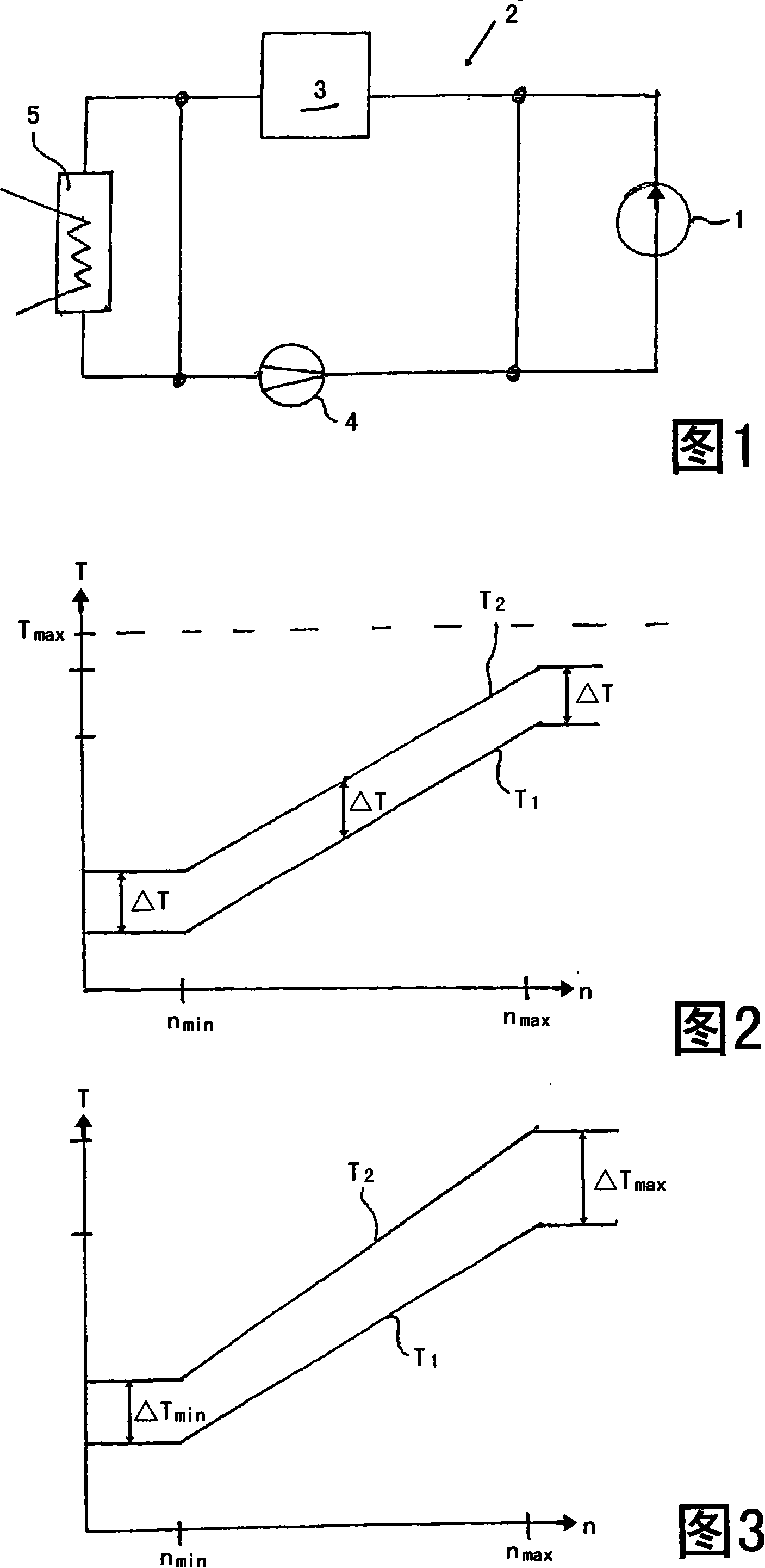
[0036] A schematic diagram of an engine cooling circuit 2 of a motor vehicle can be seen in FIG. 1 . In this engine cooling circuit 2, coolant is circulated in the circuit by means of a coolant pump 4, wherein the circuit passes through the vehicle radiator 5 (liquid-gas heat exchanger), in which the The heat is rejected to the surrounding environment. In addition, coolant flows through the vehicle drive engine 3 in order to cool the vehicle drive engine, and this coolant is the working fluid of the hydraulic brake 1 arranged in the engine cooling circuit 2 .

[0037] The arrangement of the different components in the engine cooling circuit 2 is arbitrarily selected in FIG. 1 and can be designed in different ways.

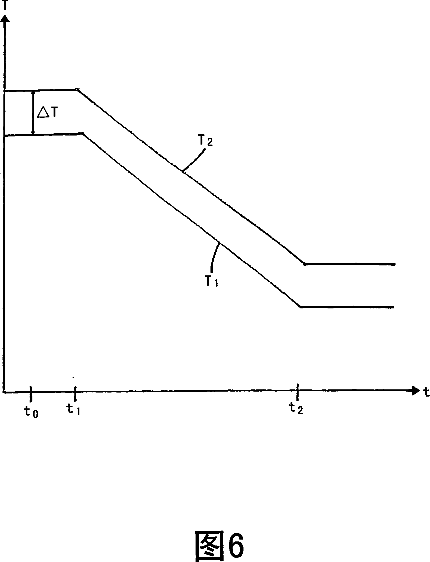
[0038] Graphs can be seen in FIGS. 2 to 5 which correspond directly to the rotational speed n of the motor vehicle's drive engine exactly two temperature curves. The two temperature curves are each in the form of a straight line with a constant slope in the rotat...


PUM


Abstract

The invention relates to a method for limiting the maximum callable braking power of hydraulic brakes in automobiles. The heat generated by the hydraulic brakes is discharged through the coolant in the engine cooling cycle of the driving engine of the automobile. Drive the engine-driven coolant pump to circulate in the engine cooling cycle, with the following steps: pre-setting the adjustment intervention temperature; pre-setting the adjustment target temperature; detecting the coolant temperature continuously or at time intervals; if the coolant temperature rises to At or above the control intervention temperature, the maximum available braking power of the hydrodynamic brake is reduced with a predetermined gradient; the gradient of the reduction depends on the difference between the control target temperature and the control intervention temperature, the control intervention Both the temperature and the control target temperature are predefined as a function of the rotational speed of the vehicle's drive engine.

Description

technical field [0001] The invention relates to two methods for limiting the maximum available braking power of hydraulic brakes in motor vehicles, if the heat generated by the hydraulic brakes is dissipated by means of coolant in the cooling circuit of the motor vehicle's engine and the coolant is controlled by means of The coolant pump driven by the vehicle drive motor circulates in the engine cooling circuit. Background technique [0002] Hydraulic brakes are also called hydraulic retarders. During braking operation, heat is generated due to fluid friction. This heat must be discharged from the hydraulic brakes so that the hydraulic brakes will not be damaged. The removal of heat from such hydraulic brakes in automobiles is usually carried out through the engine cooling circuit, that is, the coolant in the engine cooling circuit is either directly used as a working fluid for the hydraulic brake, or used to pass through a heat exchanger, Usually a liquid-liquid heat excha...

Claims


Application Information

Patent Timeline
Patent Type & Authority Applications(China)
IPC IPC(8): B60T1/087B60T8/88B60T17/18
CPCF16D57/00B60T10/02B60T17/04
Inventor H·J·贝茨
Owner VOITH TURBO GMBH & CO KG
Learn More