Novel welding device

A welding equipment and a new type of technology, applied in welding equipment, auxiliary welding equipment, welding/cutting auxiliary equipment, etc., can solve problems such as the inability to realize the effective assembly of steel rings and longitudinal bars, and the difficulty in adapting to the welding of longitudinal bars of different sizes.

Inactive Publication Date: 2016-08-03
朱玉兵
View PDF5 Cites 0 Cited by
  • Summary
  • Abstract
  • Description
  • Claims
  • Application Information

AI Technical Summary

Problems solved by technology

[0004] The above-mentioned equipment can be used to realize the welding of steel cages of different sizes, as well as the welding of steel cages of conical poles, ...

Method used


Image

  • Novel welding device
  • Novel welding device
  • Novel welding device

Examples


Embodiment Construction

[0027] In order to make the objects and advantages of the present invention clearer, the present invention will be specifically described below in conjunction with examples. It should be understood that the following words are only used to describe one or several specific implementation modes of the present invention, and do not strictly limit the protection scope of the specific claims of the present invention.

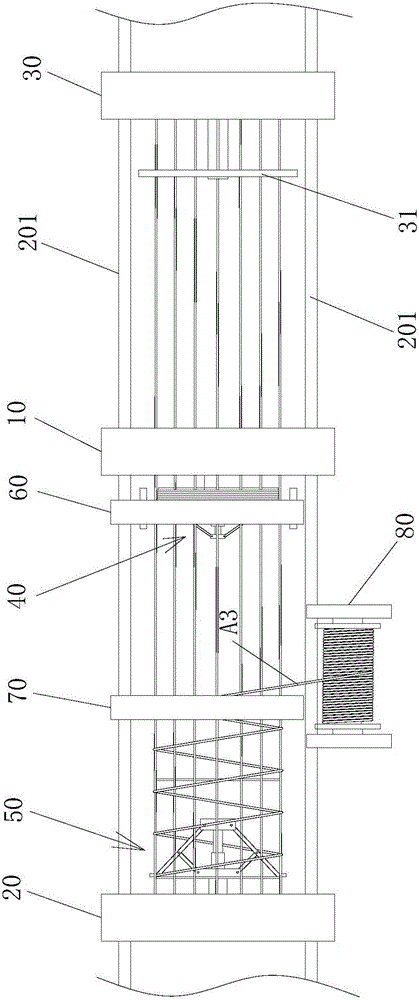
[0028] The municipal engineering provided by the invention is used to weld the steel cage, such as figure 1 As shown, it includes a fixed mounting base 10 and a movable mounting base 20 arranged oppositely, the movable mounting base 20 is installed on the first slide rail 201, and the first slide rail 201 is along the distance direction between the fixed mounting base 10 and the movable mounting base 20 Arrangement, the first drive mechanism drives the movable mount 20 to move, and the first drive mechanism can be driven by a motor or a cylinder; the fixed mount 10 ...


PUM


Abstract

The invention discloses a novel welding device. A winding rib is wound on a wire plate. The wire plate is fixed to a material distribution frame in a rotating manner. The axial direction of the wire plate and longitudinal ribs are arranged in parallel. A correction device used for correcting winding of the winding rib on the longitudinal ribs is arranged beside the material distribution frame. The correction device comprises a second beam arranged above a steel reinforcement cage, wherein a lifting table is arranged on the second beam, three correction rods which are distributed in a suspension shape are arranged on the lifting table, correction pieces sequentially arranged at intervals along winding spiral lines of the winding rib are arranged at the lower ends of the correction rods, and each correction piece is formed by a fork-shaped piece which is provided with a downward fork opening gradually increased. By means of the above provided steel reinforcement cage welding device which used for municipal engineering pile foundations, assembling and welding of the steel reinforcement cage can be effectively achieved.

Description

[0001] The present invention is a divisional application for an invention patent with the application date of July 29, 2015, the application number: 201510464600.8, and the invention name "Reinforcement Cage Welding Equipment for Municipal Engineering Pile Foundation". technical field [0002] The invention relates to the field of civil engineering, in particular to a reinforcement cage welding device for municipal engineering pile foundations. Background technique [0003] Welding reinforcement cages are often required in fields such as building pile foundations and road and bridge construction. The specific structure of the reinforcement cages is as follows: Figure 14 As shown, it includes steel reinforcement rings arranged at intervals, longitudinal reinforcement arranged at intervals around the outer circumference of the reinforcement ring, and winding reinforcement wound helically on the longitudinal reinforcement. The longitudinal reinforcement and the reinforcement rin...

Claims


Application Information

Patent Timeline
IPC IPC(8): B23K37/04B23K37/047B23K37/00B23K101/22
CPCB23K37/00B23K37/0435B23K37/047
Inventor 朱玉兵
Owner 朱玉兵
Why Eureka
Try Eureka