
Electric-heating riveting device for automobile parts

An auto parts and electric heating technology, which is applied in the field of auto parts processing, can solve problems such as rivet percussion bending, difficult end riveting, etc., to achieve safe and effective use, improve the consistency of processing quality, and reduce production costs.

Inactive Publication Date: 2016-08-03
KUNSHAN WEITEYI MOLD CO LTD
View PDF5 Cites 1 Cited by
  • Summary
  • Abstract
  • Description
  • Claims
  • Application Information

AI Technical Summary

Problems solved by technology

In some occasions, when it is necessary to use thin and hard rivets for riveting, when the end of the rivet is struck by the traditional method for riveting, it is easy to bend the rivet, and the end is normally deformed and difficult to rivet.

Method used


Image

  • Electric-heating riveting device for automobile parts
  • Electric-heating riveting device for automobile parts
  • Electric-heating riveting device for automobile parts

Examples


Embodiment 1

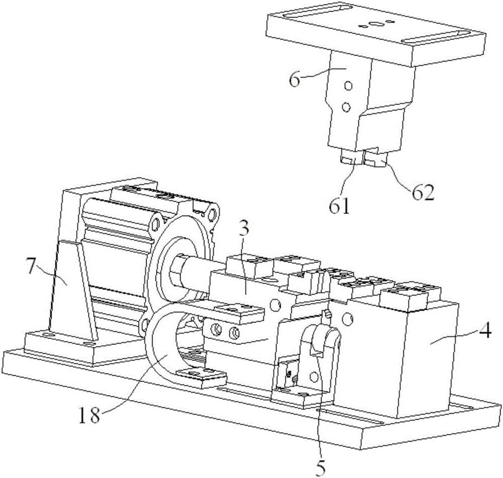
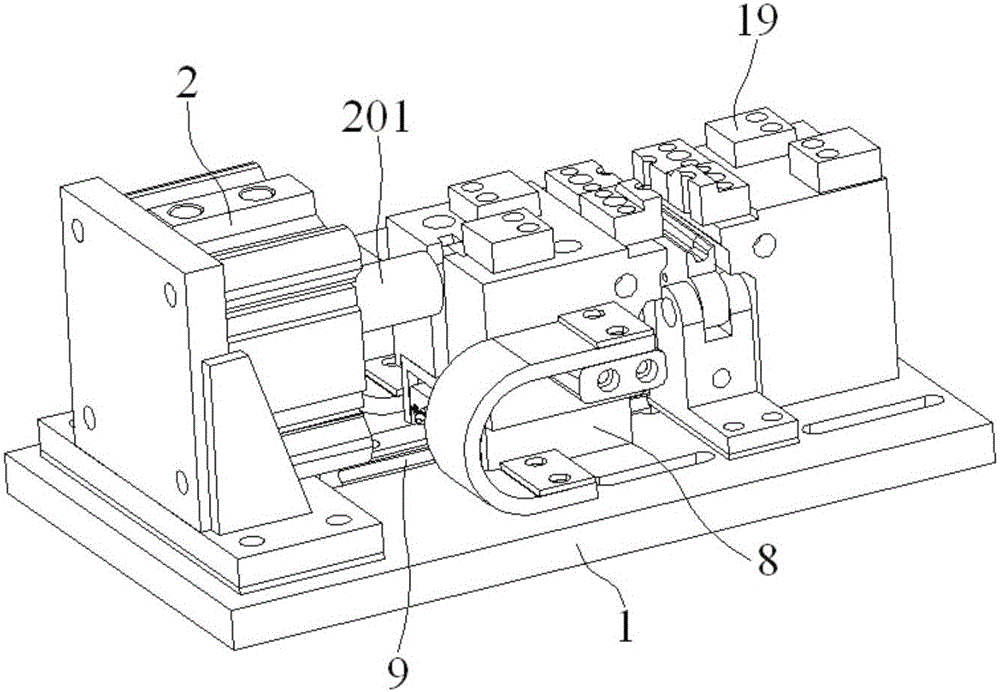
[0021] Embodiment 1: An electric heat riveting device for auto parts, including a base 1, a cylinder 2, a left clamping seat 3, a right clamping seat 4, a positioning mechanism 5 and a riveting head mechanism 6, the base 1 One end upper surface is fixed with a mounting bracket 7, the cylinder 2 is fixed on the side surface of the mounting bracket 7, the left clamping seat 3 is installed on a slide rail 9 through a slide block 8, and the right clamping seat 4 is fixed on the other end of the base 1, the left clamping seat 3 is located between the cylinder 2 and the right clamping seat 4 and the piston rod 201 of the cylinder 2 is connected to the left clamping seat 3, and the positioning mechanism 5 is located in the left clamping seat 4 Between the holding seat 3 and the right holding seat 4, the riveting head mechanism 6 is located directly above the positioning mechanism 5, and the riveting parts are placed on the upper surfaces of the left holding seat 3 and the right holdin...

Embodiment 2

[0026] Embodiment 2: An electric heat riveting device for auto parts, including a base 1, a cylinder 2, a left clamping seat 3, a right clamping seat 4, a positioning mechanism 5 and a riveting head mechanism 6, the base 1 One end upper surface is fixed with a mounting bracket 7, the cylinder 2 is fixed on the side surface of the mounting bracket 7, the left clamping seat 3 is installed on a slide rail 9 through a slide block 8, and the right clamping seat 4 is fixed on the other end of the base 1, the left clamping seat 3 is located between the cylinder 2 and the right clamping seat 4 and the piston rod 201 of the cylinder 2 is connected to the left clamping seat 3, and the positioning mechanism 5 is located in the left clamping seat 4 Between the holding seat 3 and the right holding seat 4, the riveting head mechanism 6 is located directly above the positioning mechanism 5, and the riveting parts are placed on the upper surfaces of the left holding seat 3 and the right holdin...


PUM


Abstract

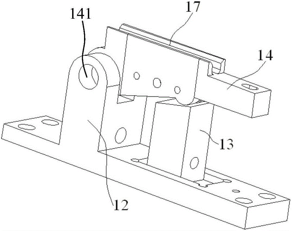
The invention discloses an electric-heating riveting device for automobile parts. The device is characterized in that an installation support is fixed on the upper surface of one end of a base, an air cylinder is fixed on the side surface of the installation support, and a left clamping base is installed on a slide rail by a slide block; a supporting block is movably installed on the rear end of the an installation plate, one end of a rotation rod is movably installed on a spindle support by a spindle, the supporting block is located under the middle of the rotation rod, one adjustment plate is installed on the side surface of the middle part of the rotation rod by bolts, a gasket is placed between the adjustment plate and the side surface of the middle part of the rotation rod, and a groove used for placement of a rivet is formed by the adjustment plate, the gasket and the side surface of the middle part of the rotation rod; and the supporting block is inlaid into a guide groove of the installation plate, a horizontal adjustment rod is inlaid into the supporting block and the spindle support in succession, and the horizontal adjustment rod drives the supporting block to move along the guide groove of the installation plate during rotation. The device disclosed by the invention has the advantages that rapid assembly and disassembly of the parts can be implemented easily; the device is applicable to processing of riveting parts with multiple specifications; and universality and safety are enhanced.

Description

technical field [0001] The invention relates to an electric heat riveting device used for auto parts, belonging to the field of auto parts processing. Background technique [0002] Riveting is a method of combining several parts with rivets. It has the characteristics of firm structure and low cost, and is widely used. In some occasions, when thin and hard rivets are required to be riveted, when the end of the rivet is struck by the traditional method for riveting, it is easy to bend the rivet, and the end is normally deformed and riveted is difficult. Contents of the invention [0003] The object of the present invention is to provide an electric heat riveting device for auto parts, which is conducive to fast loading and unloading of parts, is suitable for processing riveting parts of various specifications, and improves versatility and security. [0004] In order to achieve the above object, the technical solution adopted by the present invention is: an electric heat r...

Claims


Application Information

Patent Timeline
Patent Type & Authority Applications(China)
IPC IPC(8): B21J15/10B21J15/08B21J15/38
CPCB21J15/10B21J15/08B21J15/38
Inventor 赵国文章生陈伟
Owner KUNSHAN WEITEYI MOLD CO LTD
Learn More