
No-tillage electronic control corn compound planter

A corn seeder and seeder technology, applied in the fields of fertilizers and seeding equipment, horticulture, botanical equipment and methods, etc., can solve the problems of missing seeding, affecting the work of seed metering devices, and not being able to meet the needs of modern agricultural precision sowing, etc.

Active Publication Date: 2016-08-03
ANHUI AGRICULTURAL UNIVERSITY
View PDF5 Cites 3 Cited by
  • Summary
  • Abstract
  • Description
  • Claims
  • Application Information

AI Technical Summary

Problems solved by technology

However, as far as the current situation is concerned, there are still some problems with the no-tillage corn seeder. For example, when the amount of straw in the field is large, the general seeder is prone to ditch leg congestion and poor passability, which affects the effective sowing work.
On the other hand, we often see spoon-wheel corn seed metering devices, which mainly rely on the chain to link the walking wheels to drive the seed metering device, and rely on the gravity of the seeds to achieve seed metering, which limits the speed of seed metering operations and cannot meet the needs of large-scale planting crops. Secondly, because the driving force comes from the walking of the ground wheel, when the land is uneven or the ground wheel is at the edge of the ground, the ground wheel will slip and affect the work of our seed metering device. Sowing needs; on the other hand, single sowing cannot meet the needs of modern high-efficiency operations and crop growth

Method used


Image

  • No-tillage electronic control corn compound planter
  • No-tillage electronic control corn compound planter
  • No-tillage electronic control corn compound planter

Examples


Embodiment Construction

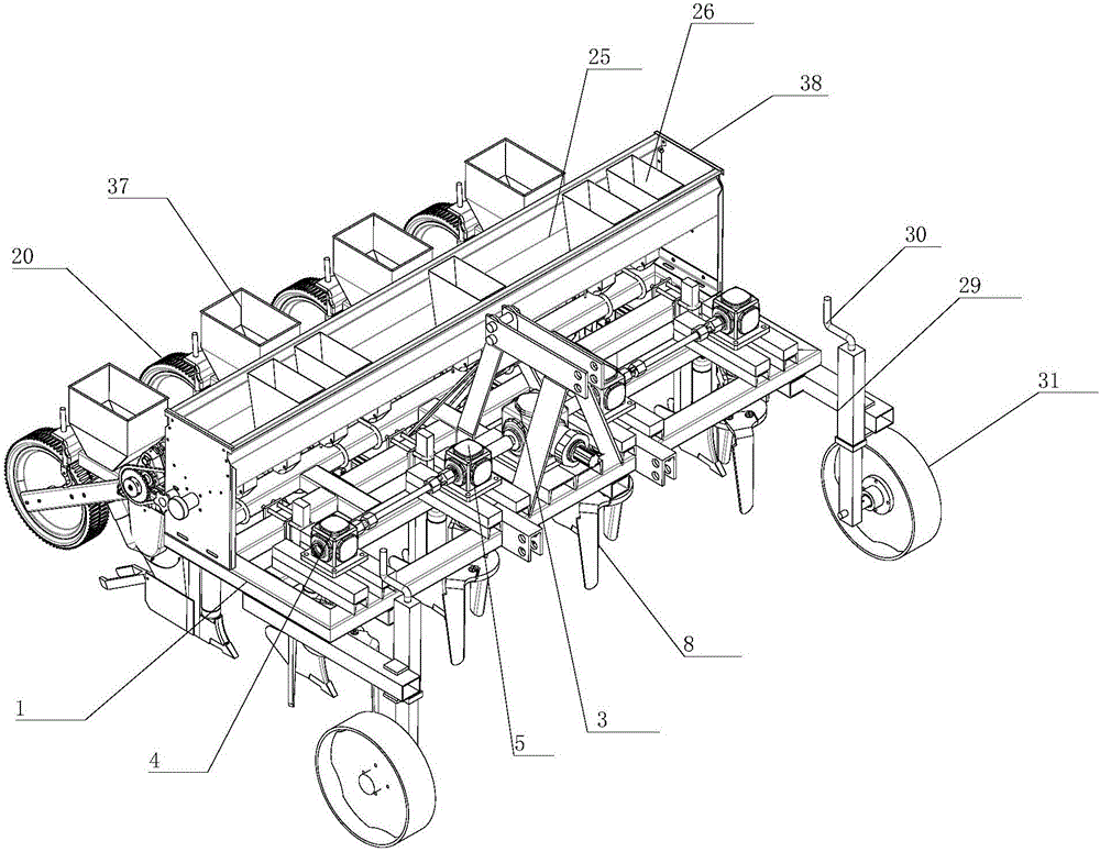
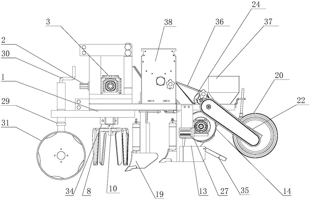
[0020] refer to figure 1 , figure 2 , image 3 , Figure 4 , Figure 5 , Figure 6 , the present invention proposes a no-tillage electronically controlled corn compound seeder, comprising a frame 1, a knife-turning cleaning mechanism, a seeding mechanism, a fertilizer discharge mechanism, a depth-limiting wheel height adjustment mechanism, a knife-drawing cleaning mechanism, a seeding mechanism, a row The fertilizer discharge mechanism and the height adjustment mechanism of the depth-limiting wheel are all installed on the frame 1, wherein:

[0021] The knife-drawing cleaning mechanism includes a spline input shaft 2, a reducer 3, a single-output commutator 4, a double-output commutator 5, a universal joint 6, a universal joint connecting shaft 7, a vertical rotary knife-drawing 8, a knife Disc 9, cutter shaft 10, spline input shaft 2 is in transmission connection with reducer 3, reducer 3 is in transmission connection with double output commutator 5, one end of universa...


PUM


Abstract

The invention provides a no-tillage electronic control corn compound planter. The planter comprises a rack, a stirring knife cleaning mechanism and a seeding mechanism, wherein the stirring knife cleaning mechanism comprises a spline input shaft, a speed reducer, a single-output commutator, a dual-output commutator, a universal joint, a universal joint connecting shaft, a vertical rotary stirring knife, a cutter head and a cutter shaft; the spline input shaft is in transmission connection with the speed reducer; the speed reducer and the double-output commutator are in transmission connection; one end of the universal joint connecting shaft is connected with the universal joint; the other end of the universal joint connecting shaft is connected with the double-output commutator; the universal joint is connected with the single-output commutator; the speed reducer, the double-output commutator and the single-output commutator are in transmission connection with the cutter shaft; the cutter shaft is connected with the cutter head; the vertical rotary stirring knife is connected with the cutter head; and the seeding mechanism comprises a control system assembly, a seeding apparatus assembly, a seeding apparatus shaft, a seeding pipe and a seeding coulter assembly. The no-tillage electronic control corn compound planter can stably work under the no-tillage operation condition; and accurate seeding and retest operation can also be achieved.

Description

technical field [0001] The invention relates to the technical field of agricultural machinery and equipment, in particular to a no-tillage electric control corn compound seeder. Background technique [0002] With the development of conservation tillage, no-till sowing is particularly important. On the premise that part or all of the crop straw is returned to the field, how to quickly and effectively sow the seeds into the field puts forward higher requirements for the sowing equipment. Modern sowing work has entered an era of rapid development. However, as far as the current situation is concerned, there are still some problems for the no-tillage corn seeder. For example, when the amount of straw in the field is large, the general seeder is prone to ditch leg congestion and poor passability, which affects effective sowing work. On the other hand, we often see spoon-wheel corn seed metering devices, which mainly rely on the chain to link the walking wheels to drive the seed...

Claims


Application Information

Patent Timeline
Patent Type & Authority Applications(China)
IPC IPC(8): A01C7/06A01G13/00
CPCA01C7/06A01G13/00Y02P60/20
Inventor 朱存玺陈黎卿余晓雨解彬彬张春岭蔡联合邵克军
Owner ANHUI AGRICULTURAL UNIVERSITY
Learn More