Replaceable edge-type rotating cutting tool

A cutting tool replacement technology, applied in the direction of manufacturing tools, milling cutting inserts, milling cutters, etc., can solve problems such as defects, and achieve the effect of suppressing defects and reducing cutting load

Active Publication Date: 2016-07-27
TUNGALOY CORP
View PDF8 Cites 6 Cited by
  • Summary
  • Abstract
  • Description
  • Claims
  • Application Information

AI Technical Summary

Problems solved by technology

Therefore, in the arrangement described in Patent Document 1, a very large load acts on the portion of the cutting edge used for both, and there is a possibility that the chip may be easily damaged from this portion.
This problem is not limited to triangular cutting inserts, but may occur in all cutting inserts using a part of the main cutting edge as an inner edge.

Method used


Image

  • Replaceable edge-type rotating cutting tool
  • Replaceable edge-type rotating cutting tool
  • Replaceable edge-type rotating cutting tool

Examples


Embodiment Construction

[0020] Hereinafter, embodiments of the present invention will be described in detail with reference to the drawings. In addition, in the following description, terms such as "upper", "lower", "front", and "rear" may be used, but these are only used to facilitate understanding and are not intended to limit the space. Absolute positional relationship and the present invention.

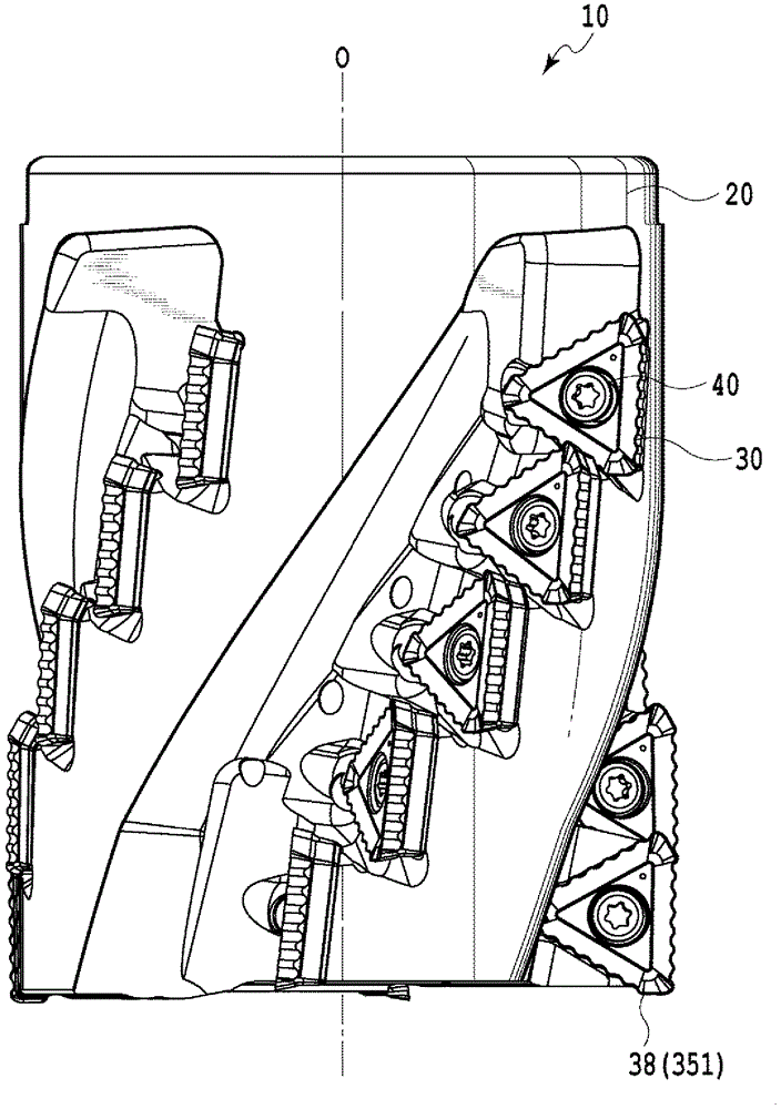
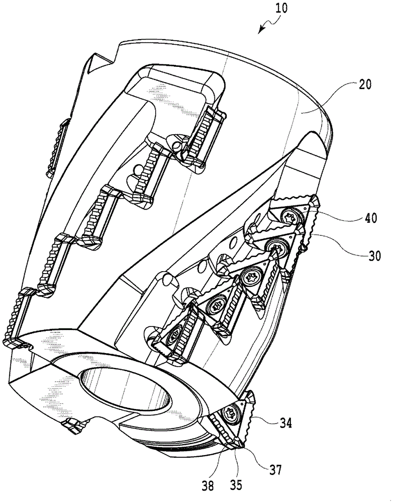
[0021] The bit replaceable rotary cutting tool 10 of this embodiment is as figure 1 and figure 2 As shown, it basically consists of a substantially cylindrical tool body 20 having a plurality of insert seats 28 and a plurality of cutting inserts 30 mounted on these insert seats 28 . The tip replaceable rotary cutting tool 10 of this embodiment may also be referred to as a roughing tool.

[0022] On the tool body 20, such as Figure 3 to Figure 5 As shown, it has a cylindrical shape composed of a first end surface 21, a second end surface 22, and an outer peripheral surface 23. The first end surface ...


PUM


Abstract

Multiple grooves (27) are formed and in each of said grooves, multiple insert seats (28) are formed and cutting inserts (30) are detachably disposed. The cutting inserts (30) have main cutting edges (34), corner cutting edges, and auxiliary cutting edges (35), and the main cutting edges (34) are formed with a wave form when viewed from the direction of the cutting face. The cutting inserts (30) are disposed so that in the rotation tracks formed by the main cutting edges (34) of the respective cutting inserts (30) when the roughing cutter (10) is rotated around the rotation center axis (O), the wave phases of the rotation tracks formed by adjacent cutting inserts (30) in a single groove (27) in the direction along the rotation center axis (O) coincide, and at least some of the cutting inserts (30) are disposed so that the rotation tracks formed by some of the cutting edge portions overlap each other in the rotation center axis (O) direction. As a result, even when said cutting edge portions are used as a main cutting edge portion and as an inner blade, cutting load is reduced and damage is limited.

Description

technical field [0001] The present invention relates to a rotary cutting tool with replaceable bits. More specifically, the present invention relates to a tip replaceable rotary cutting tool in the form of a roughing tool to which a plurality of cutting inserts are detachably mounted. Background technique [0002] Conventionally, there is a tool in which a plurality of grooves are formed on the outer peripheral surface of a cylindrical tool body from the distal end side toward the base end side, and a plurality of cutting inserts are detachably mounted in each groove in the tool rotational axis direction. Head replaceable rotary cutting tool. Generally, a rotary cutting tool having such a shape is called a roughing tool. In the roughing tool, a plurality of cutting inserts are arranged in the tool rotation axis direction, so the length of the substantial cutting edge is long, and the depth of cut can be made large. Therefore, high-efficiency machining can be realized. ...

Claims


Application Information

Patent Timeline
Patent Type & Authority Applications(China)
IPC IPC(8): B23C5/10B23C5/20
CPCB23C5/109B23C2200/0477B23C2200/206B23C2210/28B23C5/202B23C5/10B23C5/20B23C2220/60
Inventor 大塚润
Owner TUNGALOY CORP
Why Eureka
Try Eureka