
Rotary dehumidifier-type condensation dehumidification device for metal-clad equipment and control method of rotary dehumidifier-type condensation dehumidification device

A rotary dehumidifier and metal armoring technology, applied in the direction of humidity control, non-electric variable control, control/regulation system, etc., can solve the problem of fast aging of electric heating devices, shortening the service life of insulating materials, and uneven internal temperature distribution To achieve the effect of ensuring safe and stable operation and removing condensation

Inactive Publication Date: 2016-07-27
STATE GRID CORP OF CHINA +2
View PDF8 Cites 6 Cited by
  • Summary
  • Abstract
  • Description
  • Claims
  • Application Information

AI Technical Summary

Problems solved by technology

[0003] The current condensation dehumidification method for metal armored equipment is generally to install an electric heater inside to increase the internal temperature and avoid condensation of water vapor. There are problems: 1) The electric heating device has been put into operation for many years and consumes a lot of electric energy. Poor economy; 2) When the temperature is high, the internal temperature of the metal armored equipment will be too high, shortening the service life of the insulating material; 3) The electric heating dehumidification device can only be arranged in a part of the metal armored equipment, and the internal temperature distribution Uneven, the larger the internal space, the worse the heating effect and the worse the dehumidification effect; 4) The aging speed of the electric heating device is faster, and there is a greater risk of fire

Method used


Image

  • Rotary dehumidifier-type condensation dehumidification device for metal-clad equipment and control method of rotary dehumidifier-type condensation dehumidification device
  • Rotary dehumidifier-type condensation dehumidification device for metal-clad equipment and control method of rotary dehumidifier-type condensation dehumidification device

Examples


Embodiment 1

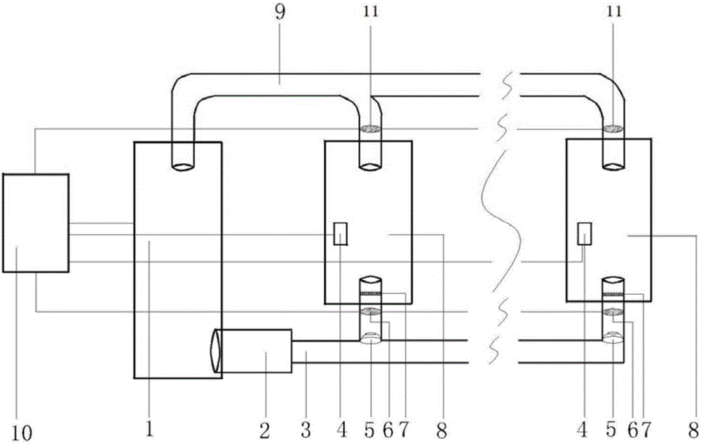
[0050] The rotary dehumidifier 1 is produced by Wuxi Yongbang Dehumidification Equipment Co., Ltd., the model is ZCM-350, and the rated humidity is 4.8kg / h; the static pressure box 2 is made of 304 stainless steel plate; the air inlet pipe 3 and the return air pipe 9 is self-processed with 304 stainless steel; the temperature and humidity meter 4 is the W4052 temperature and humidity transmitter produced by Tean Instrument Equipment Co., Ltd., the temperature measurement range is -40 ° C ~ 150 ° C, and the relative humidity measurement range is 5% ~ 110%; The spherical air outlet 5 is produced by Shanghai Eponair Ventilation Equipment Co., Ltd., the model is TE065, and the diameter of the air outlet is 80mm; the air inlet valve 6 and the return air valve 11 adopt the D941W electric ventilation butterfly valve produced by Wuhan Great Control Valve Co., Ltd. ;Grille wind deflector 7 is processed by 304 stainless steel plate; metal armored equipment 8 is KYN28A 10kV switch cabinet...


PUM


Abstract

The invention discloses a rotary dehumidifier type condensation dehumidification device for metal armored equipment and a control method thereof. The device includes a rotary dehumidifier, a ventilation unit and an automatic condensation dehumidification controller; On the installed equipment, it is connected with the rotary dehumidifier through the air inlet pipe and the return air pipe; the device has a simple structure and a high degree of automation, which realizes the automatic remote control of the condensation of the metal armored equipment and greatly reduces the opening time of the dehumidification equipment. Avoid the fire risk caused by overheating of the dehumidification equipment inside the metal armored equipment; the internal humidity control of a single metal armored equipment is relatively uniform, and the humidity target value can be set arbitrarily, avoiding the phenomenon of uneven dehumidification inside the large-volume metal armored equipment , the dehumidification effect is good; the dehumidification process will not cause the internal temperature of the metal armored equipment to rise, avoiding the risk of excessive aging of the insulating material.

Description

technical field [0001] The invention belongs to the technical field of electrical engineering, and relates to a rotary dehumidifier type condensation dehumidification device for metal armored equipment and a control method thereof. Background technique [0002] When the temperature of metal armored equipment (high-voltage switchgear, HSBC, ring network cabinet, etc.) drops suddenly, condensation will often appear on its internal equipment, the insulation strength of electrical components will be greatly reduced, and a short circuit fault will occur. The phenomenon is more common in the humid climate areas in southern my country, and has become one of the serious threats to the safe and stable operation of the power system. [0003] The current condensation dehumidification method for metal armored equipment is generally to install an electric heater inside to increase the internal temperature and avoid condensation of water vapor. There are problems: 1) The electric heating d...

Claims


Application Information

Patent Timeline
IPC IPC(8): H02B1/56H02B1/28G05D22/02
CPCH02B1/56G05D22/02H02B1/28
Inventor 孙利朋李欣吴水锋赵世华叶会生
Owner STATE GRID CORP OF CHINA
Learn More