
Dual-frequency rotary joint used capable of realizing S single-frequency and X single-frequency transmission

A rotary joint, single-frequency technology, applied in the direction of electrical components, circuits, waveguide devices, etc., to achieve the effect of strong bearing capacity, low signal transmission loss, and compact structure

Inactive Publication Date: 2016-07-27
UNIT 63680 OF PLA
View PDF2 Cites 7 Cited by
  • Summary
  • Abstract
  • Description
  • Claims
  • Application Information

AI Technical Summary

Problems solved by technology

[0006] The technical problem to be solved by the present invention is to provide a rotary joint with small insertion loss, low VSWR, large power capacity, and capable of simultaneously transmitting high-power radio frequency signals in two frequency bands of S and X in order to solve the problem of S Requirements for dynamic transmission of uplink high-power signals with +X dual-frequency co-constructed antenna

Method used


Image

  • Dual-frequency rotary joint used capable of realizing S single-frequency and X single-frequency transmission
  • Dual-frequency rotary joint used capable of realizing S single-frequency and X single-frequency transmission
  • Dual-frequency rotary joint used capable of realizing S single-frequency and X single-frequency transmission

Examples


Embodiment Construction

[0030] The present invention will be further described in detail below in conjunction with the accompanying drawings and embodiments.

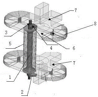
[0031] In this embodiment, a dual-frequency rotary joint for S single-frequency and X single-frequency transmission transmits radio frequency signals of S and X frequency bands at the same time in one joint, and two channels are designed for the joint to transmit S frequency band and X frequency band respectively the emission signal. During the design, the two-way rotary joints are designed separately. After the design of each joint is completed, the two-way joints are combined together, so that the whole rotary joint has the ability to transmit S and X frequency bands at the same time. Joint diagram as in figure 1 shown.

[0032] (1) Design and simulation of X-band rotary joints

[0033] The composition of the X-band joint mainly includes a circular waveguide 1, a rectangular waveguide 2, a short-circuit tube 3, and a coupling hole 4 betwe...


PUM


Abstract

The invention relates to a dual-frequency rotary joint used for S single frequency and X single frequency transmission, including an X frequency band joint and an S frequency band joint. The X frequency band joint mainly includes a circular waveguide, a rectangular waveguide and a short-circuit cylinder. The two ends of the circular waveguide are connected to each other, the rectangular waveguide is arranged on the side circular surface of the two ends of the circular waveguide, and the rectangular waveguide and the circular waveguide are connected to each other through the coupling hole; the S-band joint mainly includes a coaxial waveguide, two work points device, magic T and waveguide elbow, the coaxial waveguide and the circular waveguide are coaxially arranged, and are located outside the circular waveguide, forming a transmission channel between the coaxial waveguide and the circular waveguide, and the two power dividers are respectively located on the coaxial Both ends of the waveguide are connected to the transmission channel between the coaxial waveguide and the circular waveguide, and the two horizontal signal ports of the magic T are connected to the two signal ports of the two-power splitter through the waveguide elbow. The invention is a rotary joint capable of simultaneously transmitting high-power radio frequency signals of S and X frequency bands, so as to solve the requirement of dynamic transmission of uplink high-power signals of S+X dual-frequency co-constructed antennas.

Description

technical field [0001] The invention relates to a microwave component, in particular to a dual-frequency rotary joint capable of simultaneously transmitting S single frequency and X single frequency. Background technique [0002] The radio frequency signal rotary joint is the core component of the radar feeder system. Its main job is to ensure that the feeder system device (rotary joint) used for high-power microwave signal transmission rotates relative to the mechanical position (generally 360o unlimited) movement. The transmission signal is electrically low-loss and smoothly transmitted. The design work of the rotary joint is very complicated and cumbersome. The problem often encountered by the rotary joint designer is: to give the size limit of the rotary joint, and then design the electrical scheme. This requires the designer to combine the design theory and working principle of the rotary joint with the actual workplace, and creatively propose a feasible solution. [...

Claims


Application Information

Patent Timeline
Patent Type & Authority Applications(China)
IPC IPC(8): H01P1/06
CPCH01P1/066
Inventor 毛南平房新兵何剑伟瞿元新潘高峰李红艳刘为民刘洋刘四方徐光明夏利利薛军王萍
Owner UNIT 63680 OF PLA
Learn More