
Sensor detection circuit

A detection circuit and sensor technology, applied in the direction of measuring electrical variables, measuring resistance/reactance/impedance, instruments, etc., can solve problems such as complex circuits, affecting oscillation frequency, power fluctuations, etc., and achieve strong anti-interference ability and high sensitivity.

Active Publication Date: 2016-07-27
SICHUAN UNIVERSITY OF SCIENCE AND ENGINEERING
View PDF5 Cites 0 Cited by
  • Summary
  • Abstract
  • Description
  • Claims
  • Application Information

AI Technical Summary

Problems solved by technology

[0006] ④ The circuit is complex, and frequency stabilization measures must be taken; the output of the circuit is relatively nonlinear
[0015] (2) Influence of power fluctuation
Obviously both affect the oscillation frequency

Method used


Image

  • Sensor detection circuit
  • Sensor detection circuit
  • Sensor detection circuit

Examples


specific Embodiment 1

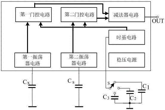
[0038] Such as figure 1 The sensor detection circuit shown is applicable to the detection circuit of a general multivibrator, including a first oscillating circuit and a first gating circuit connected to it; it also includes a second oscillating circuit and a second gating circuit connected to it; The structure of the first oscillating circuit and the second oscillating circuit is the same; the structure of the first gating circuit and the second gating circuit is the same; A subtractor circuit; the output of the subtractor circuit is the output of the whole circuit.

[0039] For the detection circuit of a general multivibrator, the oscillating circuit generates a pulse wave and does not require a frequency-to-digital conversion circuit. The external capacitor Cx is a capacitive sensor, and Cs is a fixed capacitor with the same structure as Cx; it is composed of Cs and Cx. The differential capacitance sensor can also make the detection sensitivity doubled, and the output line...

specific Embodiment 2

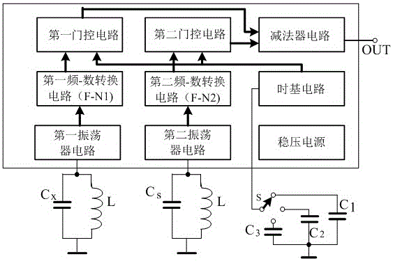
[0040] On the basis of specific embodiment one, such as figure 2 As shown, it is suitable for the detection circuit of general LC sine wave oscillator. It also includes a first frequency-to-digital conversion circuit F-N1 connected between the first oscillating circuit and the first gating circuit, and a second frequency-to-digital conversion circuit connected between the second oscillating circuit and the second gating circuit Circuit F-N2; the first frequency-to-digital conversion circuit and the second frequency-to-digital conversion circuit have the same structure.

[0041] The capacitor Cx externally connected to the circuit is a capacitive sensor, Cs is a fixed capacitor with exactly the same structure as Cx, and L is an externally connected fixed inductance exactly the same. If an inductance sensor is used, Cs and Cx are fixed capacitors, the inductance connected to the first oscillating circuit is a fixed inductance, and the inductance connected to the second oscilla...

specific Embodiment 3

[0042] On the basis of the specific embodiment 1 or 2, a voltage stabilizing circuit connected to the power supply terminals of each circuit is also included.


PUM


Abstract

The invention provides a sensor detection circuit. The sensor detection circuit comprises a first oscillating circuit and a first gating circuit connected with the first oscillating circuit, and a second oscillating circuit and a second gating circuit connected with the second oscillating circuit. The construction of the first oscillating circuit is identical with that of the second oscillating circuit. The construction of the first gating circuit is identical with that of the second gating circuit. The sensor detection circuit further comprises a subtracter circuit which is connected with output of the first gating circuit and the second gating circuit. The output of the subtracter circuit is the output of the whole circuit. According to the invention, the frequency stability problem of a frequency conversion detection circuit is solved, the normal detection of a capacitance or inductive sensor is not influenced, the stability is high, the sensor detection circuit is not liable to be influenced by the outer environment, and the circuit structure is relatively simple and practical.

Description

technical field [0001] The invention relates to a sensor detection circuit, in particular to a sensor detection circuit suitable for detection circuits of capacitance and inductance sensors. Background technique [0002] In the detection circuit of capacitive and inductive sensors, the detection circuit can be divided into bridge type detection circuit, diode double T type detection circuit, operational amplifier type detection circuit, differential pulse width modulation type detection circuit and frequency modulation type detection circuit. Various detection circuits have their own characteristics and requirements, but the frequency conversion detection circuit has the highest detection sensitivity. Frequency conversion detection circuit has the following advantages: [0003] ① High sensitivity, can measure the displacement change of 0.01μm level, or even higher. [0004] ②The frequency output is easy to obtain digital output without using A / D converter; [0005] ③Can o...

Claims


Application Information

Patent Timeline
Patent Type & Authority Applications(China)
IPC IPC(8): G01R27/26
CPCG01R27/26G01R27/2605
Inventor 王明灼姜涛
Owner SICHUAN UNIVERSITY OF SCIENCE AND ENGINEERING
Learn More