
Rocket launcher fire extinguishing bomb launching device used for unmanned aerial vehicle fire extinguishment

A launching device and bazooka technology, which is applied in launching devices, aircraft parts, transportation and packaging, etc., can solve the problems of small number of aerosol fire extinguishing bombs, poor practicability, difficulty in fixed-point hovering of rotorcraft, etc., and achieve long escape time and guarantee Fire extinguishing effect, effect of delaying burning rate

Pending Publication Date: 2016-07-27
SANYI AVIATION TECH NANTONG CO LTD
View PDF11 Cites 2 Cited by
  • Summary
  • Abstract
  • Description
  • Claims
  • Application Information

AI Technical Summary

Problems solved by technology

However, because the device is a mechanical structure, the horizontal ejection distance of the fired fire extinguishing bomb depends on the elastic modulus of the spring and the size of the compression distance. Generally, the ejection distance is relatively short, about 10m. When the fire is large, the heat wave will cause the rotorcraft Difficulty hovering outside the window
Moreover, the number of aerosol fire extinguishing bombs carried by this device is relatively small, generally 1-3, and the practicability is poor

Method used


Image

  • Rocket launcher fire extinguishing bomb launching device used for unmanned aerial vehicle fire extinguishment
  • Rocket launcher fire extinguishing bomb launching device used for unmanned aerial vehicle fire extinguishment
  • Rocket launcher fire extinguishing bomb launching device used for unmanned aerial vehicle fire extinguishment

Examples


Embodiment Construction

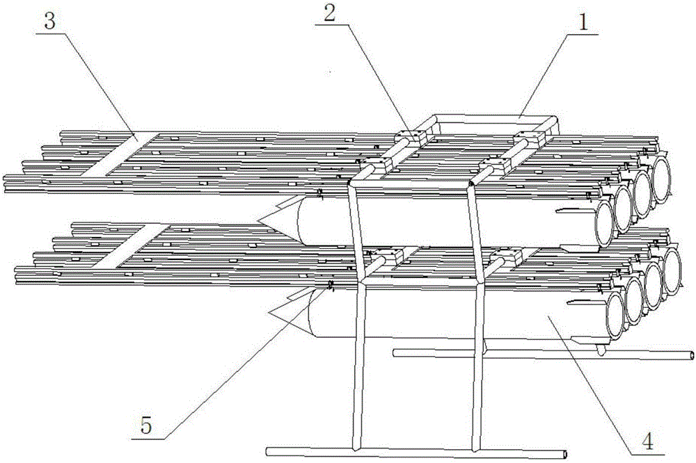
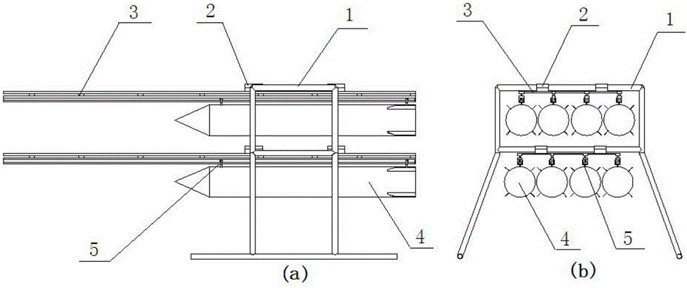
[0032] This embodiment is an ammunition launching device used in unmanned aerial vehicle firefighting, including a landing gear 1 of an unmanned aerial vehicle, a clamp block 2, a rocket launcher hanger 3, a rocket launcher 4, and a launching guide wheel 5. The rocket launcher hanger 3 has two layers, which are respectively fixed on the landing gear 1 by clamping blocks 2 . Each bazooka 4 is hung on the launching guide wheel 5 that is positioned at each bazooka hanger lower surface respectively.

[0033] The upper surface of the undercarriage 1 has threaded holes for being fixedly connected with the lower floor of the UAV, and during use, the undercarriage 1 is fixed on the lower floor of the UAV through a connector.

[0034]The landing gear 1 is an integral frame structure. The undercarriage consists of a hanger and a pair of support frames. The hanger is a square frame bar member welded by circular hollow aluminum tubes; the pair of support frames are fixed on both sides o...


PUM


Abstract

The invention provides a rocket launcher fire extinguishing bomb launching device used for unmanned aerial vehicle fire extinguishment. Two layers of rocket launcher hanging brackets are arranged and are fixed on an undercarriage through clamping blocks respectively. Each rocket launcher is hung on a launching guide rail located on the lower surface of each rocket launcher hanging bracket. The undercarriage is of an integrated framework structure. The undercarriage is composed of a hanging bracket and a pair of supporting frames. The supporting frames are fixed at the two sides of the lower surface of the hanging bracket. In the square hanging bracket, the lower surface of an upper edge frame and the lower surface of a lower edge frame are mounting surfaces of the rocket launcher hanging brackets. The pair of supporting frames can be formed through welding round hollow aluminum pipes. The supporting frames are fixed at the two sides of the lower surface of the hanging bracket in an external splayed shape. The rocket launcher fire extinguishing bomb launching device is located at the bottom of a cover plate of an unmanned aerial vehicle and is mounted on a lower bottom plate of the unmanned aerial vehicle; the rocket launcher fire extinguishing bomb launching device carries a rocket launcher aerosol fire extinguishing bomb for put out fire of a fire scene of a high-rise building, and the combustion speed can be effectively delayed so that relatively long escaping time is won for people.

Description

technical field [0001] The invention relates to the field of fire-fighting devices for high-rise buildings, in particular to a bazooka fire-extinguishing bomb launching device for unmanned aerial vehicle fire-fighting. Background technique [0002] The fire extinguishing of high-rise buildings is one of the three major world problems in the field of fire protection, especially for high-rise buildings above 100m, and there is no effective solution at present. The height of traditional ladders in general cities is 50-100 meters, while most of the current high-rise buildings are 100-300 meters. Even if equipped with high-strength hydraulic pumps, it is difficult to control the spread of super-high-rise fires above 100 meters. [0003] Compared with the traditional water fire extinguishing system, aerosol fire extinguishing is gradually becoming the trend of fire extinguishing. Aerosol fire extinguishing uses the principle of negative catalysis and destruction of the combustion...

Claims


Application Information

Patent Timeline
IPC IPC(8): B64D1/06
CPCB64D1/06
Inventor 李占科魏辰宋笔锋安伟刚宣建林黄拓薛鲲岳常欣
Owner SANYI AVIATION TECH NANTONG CO LTD
Learn More