Inkjet printing apparatus
An inkjet recording and inkjet head technology, applied in printing devices, printing and other directions, can solve problems such as instability and inkjet head contamination, and achieve the effects of improving quality, reducing individual differences, and reducing contamination
- Summary
- Abstract
- Description
- Claims
- Application Information
AI Technical Summary
Problems solved by technology
Method used
Image
Examples
no. 1 approach
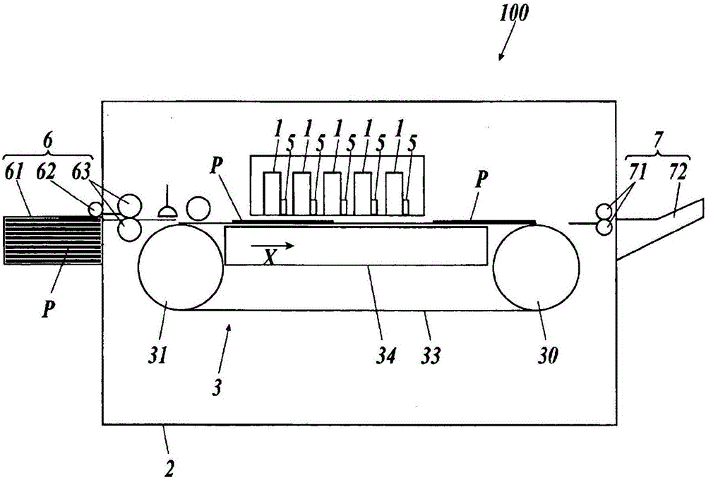
[0048] Hereinafter, the inkjet recording device 100 of the first embodiment will be described with reference to the drawings.
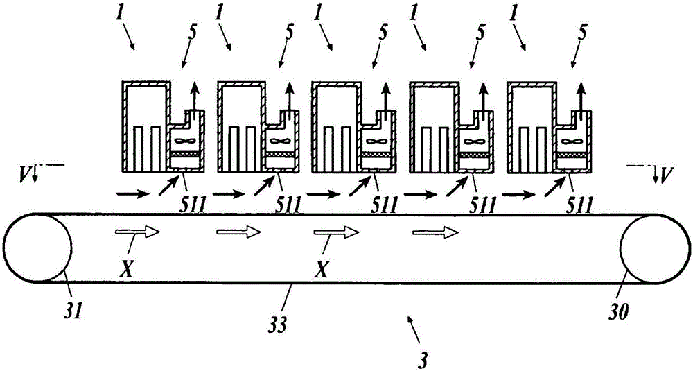
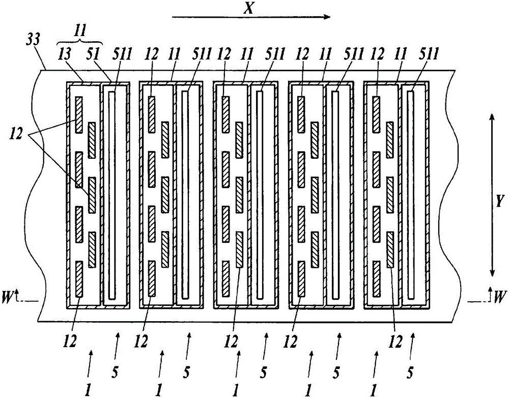
[0049] Such as figure 1 As shown, the inkjet recording device 100 is an inkjet line printer, and ink is ejected from an inkjet head 12 serving as an ink ejection unit to a recording medium P to form an image on the recording medium P. The inkjet line printer has nozzles over the same range as the maximum width of the inkjet head unit that has a plurality of inkjet heads that can form an image in the medium width direction perpendicular to the conveyance direction, and is carried out on the conveyed recording medium. An image is formed without moving the inkjet head unit in the medium width direction.
[0050] In addition, the inkjet recording apparatus 100 exemplified below performs image formation on a flat surface of a sheet-shaped cut paper or a film base material as the recording medium P. As shown in FIG.
[0051] In addition, in the following ...
no. 2 approach
[0142] An inkjet recording device 100B according to the second embodiment will be described. Regarding the configuration of the inkjet recording device 100B, the same configurations as those of the inkjet recording device 100 described above are denoted by the same reference numerals and redundant descriptions are omitted.
[0143] The inkjet recording apparatus is not limited to a structure in which the recording medium P is conveyed by a belt, for example, as Figure 11 As shown, it can also be applied to a drum type line inkjet printer.
[0144] In this case, the inkjet recording apparatus 100B has five inkjet head units 1 for discharging inks of white (W), yellow (Y), magenta (M), cyan (C), and black (K). , a support frame 2B, a conveyance unit 3B, five suction mechanisms 5 provided on the downstream side of each inkjet head unit 1 in the conveyance direction, a supply unit 6 , and a discharge unit 7 . In addition, the structures and functions of the inkjet head unit 1 ,...
no. 3 approach
[0162] based on Figure 12 An inkjet recording apparatus 100C according to the third embodiment will be described. Regarding the configuration of the inkjet recording apparatus 100C, the same configurations as those of the inkjet recording apparatus 100 described above are denoted by the same reference numerals and redundant descriptions are omitted.
[0163] In the inkjet recording apparatuses 100 and 100B described above, paper or a sheet is used as a recording medium, but in this inkjet recording apparatus 100C, an image is formed on a recording medium Q made of tiles.
[0164] In this inkjet recording apparatus 100C, each inkjet head unit 1 , support frame 2 , conveyance unit 3 , and each suction mechanism 5 have the same configuration as that of the inkjet recording apparatus 100 .
[0165] However, since the recording medium Q of ceramic tiles is thicker than paper and sheets, each inkjet head unit 1 and the suction mechanism 5 are additionally provided with respect to ...
PUM
 Abstract
Description
Claims
Application Information
 - R&D Engineer
- R&D Manager
- IP Professional
- Industry Leading Data Capabilities
- Powerful AI technology
- Patent DNA Extraction
Browse by: Latest US Patents, China's latest patents, Technical Efficacy Thesaurus, Application Domain, Technology Topic, Popular Technical Reports.
© 2024 PatSnap. All rights reserved.Legal|Privacy policy|Modern Slavery Act Transparency Statement|Sitemap|About US| Contact US: help@patsnap.com


