
Linear constant-current circuit for light modulation of silicon controlled rectifier

A linear constant current circuit and linear constant current technology, applied in the direction of light sources, electric light sources, electrical components, etc., can solve the problems of narrow dimming and dimming range of silicon controlled rectifiers, low utilization rate of LED light strings, affecting normal operation of current, etc. , to achieve the effect of improving utilization rate, reducing circuit loss and ensuring work efficiency

Active Publication Date: 2016-07-20
SUZHOU ZHIPU XINLIAN ELECTRONICS TECH
View PDF4 Cites 18 Cited by
  • Summary
  • Abstract
  • Description
  • Claims
  • Application Information

AI Technical Summary

Problems solved by technology

[0007] To sum up, in the existing linear constant current circuit used in LED thyristor dimming in the market, the LED light string needs to highly match the input voltage with the number of LEDs connected in series: the lower the number of LEDs connected in series, the greater the loss , and even affect the normal operation of the current; the higher the number of LEDs connected in series, the lower the utilization rate of the LED light string, and the narrower the dimming range of the thyristor dimming

Method used


Image

  • Linear constant-current circuit for light modulation of silicon controlled rectifier
  • Linear constant-current circuit for light modulation of silicon controlled rectifier
  • Linear constant-current circuit for light modulation of silicon controlled rectifier

Examples


Embodiment 1

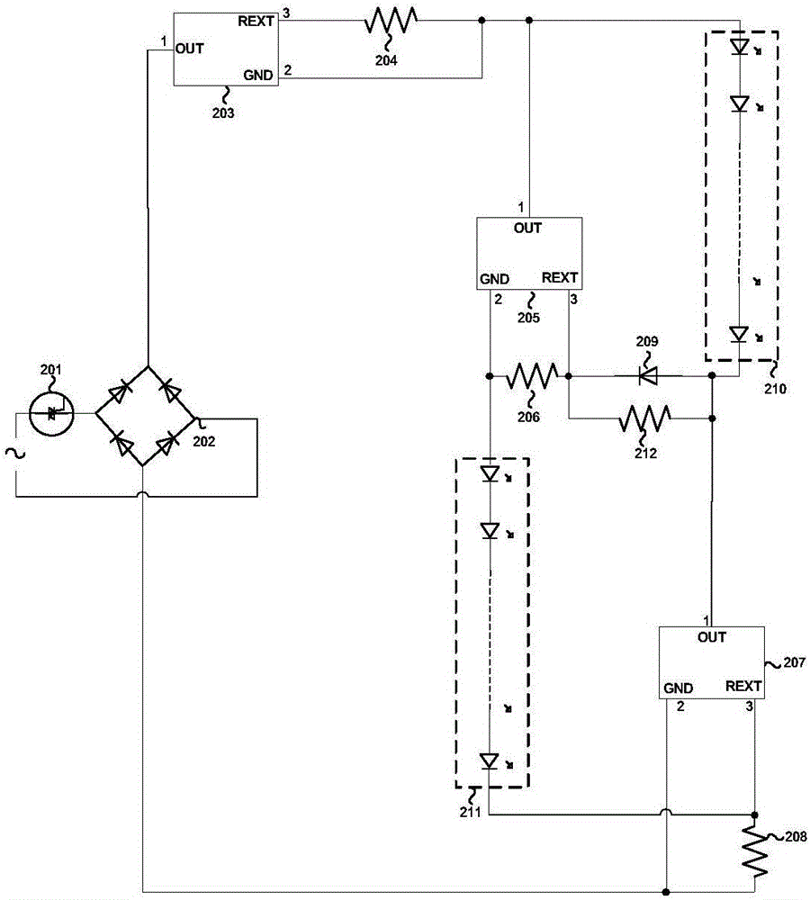
[0029] Such as image 3 As shown, the present invention provides a linear constant current circuit for thyristor dimming, including a thyristor dimmer 201, a rectifier bridge 202, a first linear constant current chip 203, a first current adjusting resistor 204, The second linear constant current chip 205, the second current regulating resistor 206, the third linear constant current chip 207, the third current regulating resistor 208, the diode 209, the first LED light string 210, the second LED light string 211, and maintaining current regulation Resistance 212.

[0030] Among them, the thyristor dimmer 201 is electrically connected in series with the AC input voltage source; the two input ends of the rectifier bridge 202 are respectively electrically connected to the thyristor dimmer 201 and the AC input voltage source; the first linear constant current chip 203 The OUT terminal is electrically connected to the positive output terminal of the rectifier bridge 202; one end of the...

Embodiment 2

[0037] Such as Picture 8 As shown, the present invention provides a linear constant current circuit for thyristor dimming, including a thyristor dimmer 201, a rectifier bridge 202, a first linear constant current chip 203, a first current adjusting resistor 204, The second linear constant current chip 205, the second current regulating resistor 206, the third linear constant current chip 207, the third current regulating resistor 208, the diode 209, the first LED light string 210, the second LED light string 211, maintaining current regulation The resistor 212 and the sustain current control chip 213.

[0038] The thyristor dimmer 201 is electrically connected in series with the AC input voltage source; the two input ends of the rectifier bridge 202 are respectively electrically connected to the thyristor dimmer 201 and the AC input voltage source; the OUT terminal of the first linear constant current chip 203 Electrically connected to the positive output end of the rectifier br...


PUM


Abstract

The invention belongs to the field of LED control, and mainly discloses a linear constant-current circuit for light modulation of a silicon controlled rectifier. Three sets of linear constant-current modules are combined with two sets of LED lamp strings. Furthermore current adjusting resistors with different resistances are arranged according to the positions of the three sets of linear constant-current modules in a circuit, thereby adaptively parallelly connecting or serially connecting the two sets of LED lamp strings according to the magnitude of the input voltage. The linear constant-current circuit has advantages of effectively improving utilization rate of the LED lamp strings, increasing light modulation range of the silicon controlled rectifier, ensuring high operation efficiency of the circuit and reducing circuit loss.

Description

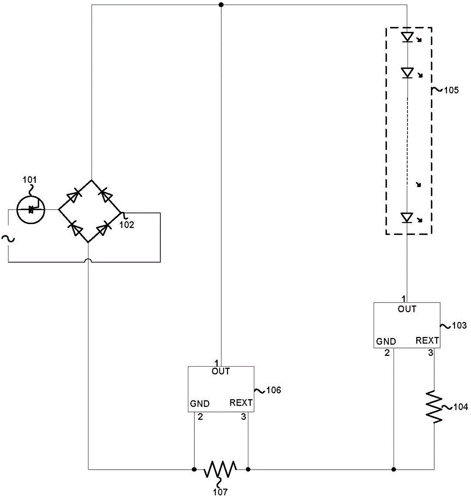
Technical field [0001] The invention belongs to the field of LED control, and in particular relates to a linear constant current circuit for thyristor dimming. Background technique [0002] LED high-voltage linear constant current technology has been more and more widely used due to its simple solution, low cost, no high-frequency transformer and no EMC problems, and is gradually applied to LED thyristor dimming. [0003] The existing linear constant current circuits used in LED thyristor dimming in the market, such as figure 1 As shown, the input AC voltage source is electrically connected in series with a thyristor dimmer 101, and then connected to the two input ends of the rectifier bridge 102. After being rectified by the rectifier bridge 102, the LED light string 105 is electrically connected to the positive terminal, and the LED light string 105 is negative. The terminal is electrically connected to the main control chip 103, the current flowing through the LED light string 1...

Claims


Application Information

Patent Timeline
IPC IPC(8): H05B33/08H05B44/00
CPCH05B45/00Y02B20/30
Inventor 杨全戎淑虎曹亚军边彬陈畅
Owner SUZHOU ZHIPU XINLIAN ELECTRONICS TECH
Learn More