Bicolor stimulated raman scattering imaging system based on bi-channel orthogonal detection

A stimulated Raman scattering and imaging system technology, applied in Raman scattering, material excitation analysis, etc., can solve problems such as error, inability to detect Raman vibration frequency in real time, optical delay line for a certain time, etc., to achieve improvement Low cost, promotion of clinical application, and the effect of eliminating spectral errors

Active Publication Date: 2016-07-20
FUDAN UNIV
View PDF6 Cites 11 Cited by
  • Summary
  • Abstract
  • Description
  • Claims
  • Application Information

AI Technical Summary

Problems solved by technology

But its main disadvantage is that it takes a certain amount of time to adjust the position of the optical delay line, and it cannot detect two or more Raman vibration frequencies in real time.
This is bound to introduce errors for the measured object that requires two-color imaging and moves quickly

Method used


Image

  • Bicolor stimulated raman scattering imaging system based on bi-channel orthogonal detection
  • Bicolor stimulated raman scattering imaging system based on bi-channel orthogonal detection
  • Bicolor stimulated raman scattering imaging system based on bi-channel orthogonal detection

Examples


Embodiment Construction

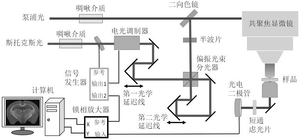
[0020] The steps to build and test a two-color stimulated Raman imaging system are as follows:

[0021] (1) Transformation of Stokes light.

[0022] Such as figure 1 As shown, the two-color stimulated Raman imaging system built in the present invention is based on the hyperspectral stimulated Raman imaging system. The pulses of pump light and Stokes light, both of which are linearly polarized, are time-stretched by a chirped medium. The repetition frequency of the laser pulse collected in the Stokes optical path is used as the reference frequency of the signal generator to generate the modulation frequency of the optoelectronic modulator and the resolution reference frequency of the lock-in amplifier (laser repetition frequency is 80MHz, electro-optic modulation and phase-locked The demodulation frequency of the amplifier is 20MHz). Electro-optic modulators can periodically change the polarization properties of Stokes light. In this way, when the Stokes light encounters th...


PUM


Abstract

The invention belongs to the technical field of nonlinear optical imaging, and relates to a bicolor stimulated raman scattering imaging system based on bi-channel orthogonal detection. With skillful combination of the spectrum focusing method and bi-channel orthogonal output of a lock-phase amplifier, the light path is simple in design, and the bicolor stimulated raman scattering imaging system is low in modification cost, and stable as adjustment of any photoelectric devices is not needed after optimization. The system can realize that fat and protein can be imaged by double spectrum in real time, and image information can be provided in real time for pathological examination; spectrum errors caused by sample moving are eliminated, and technical support is provided for living body and dynamic detection. For spectral imaging of the samples containing various components or imaging of large-area samples, imaging speed can be increased by more than 2 times. The bicolor stimulated raman scattering imaging system can greatly promote clinical application of the stimulated raman imaging technology.

Description

technical field [0001] The invention belongs to the field of nonlinear optical imaging, in particular to a stimulated Raman imaging system capable of simultaneously detecting two Raman vibration frequencies. Background technique [0002] Stimulated Raman imaging technology is a non-linear optical imaging method developed rapidly in recent years. It is an organic combination of Raman scattering and stimulated radiation technology. Therefore, the stimulated Raman scattering technology has the advantages of the above two technologies: 1. The intensity of the stimulated Raman scattering is linearly related to the concentration of the analyte; 2. The signal strength is high, the signal-to-noise ratio is high, and the image quality is good; 3. , no non-resonant background interference, and no spectral distortion. [0003] However, each single scan of the stimulated Raman imaging system can only be imaged for one Raman vibration frequency, that is, monochromatic imaging. This is ...

Claims


Application Information

Patent Timeline
Patent Type & Authority Applications(China)
IPC IPC(8): G01N21/65
CPCG01N21/65
Inventor 贺若愚徐永奎张莉丽
Owner FUDAN UNIV
Why Eureka
Try Eureka