Tool trolley

A trolley and tool technology, applied in the direction of manufacturing tools, metal processing equipment, assembly machines, etc., can solve the problems of damage to the transmission device, waste of electric energy, and high requirements for assembly time.

Inactive Publication Date: 2016-07-20
TIANJIN YUEFENG TECH
View PDF0 Cites 0 Cited by
  • Summary
  • Abstract
  • Description
  • Claims
  • Application Information

AI Technical Summary

Problems solved by technology

[0002] In the production line of some processes, the workpiece needs to be assembled from multiple angles. After the assembly is completed, the workpiece needs to be moved to another process. Generally, a transfer device is used to place the workpiece on the conveyor belt. Multiple people assemble it and move it after completion. to another pr...

Method used


Image

  • Tool trolley
  • Tool trolley
  • Tool trolley

Examples


Embodiment Construction

[0017] The following will clearly and completely describe the technical solutions in the embodiments of the present invention with reference to the accompanying drawings in the embodiments of the present invention. Obviously, the described embodiments are only some, not all, embodiments of the present invention. Based on the embodiments of the present invention, all other embodiments obtained by persons of ordinary skill in the art without making creative efforts belong to the protection scope of the present invention.

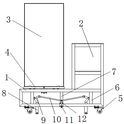
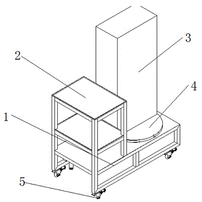
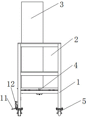
[0018] The present invention provides such Figure 1-4 A kind of tool trolley shown, comprises underframe 1, and described underframe 1 is provided with support bar between two upper and lower layers; Described underframe 1 top is provided with tool table 2 and disc table 4, and described disc The workbench 4 is connected with the base frame 1 through a rotating bearing, and the workpiece 3 is placed on the 4 sides of the disc workbench; a linkage mechanism is...


PUM


Abstract

The invention discloses a tool trolley comprising an underframe, wherein supporting rods are arranged between an upper layer and a lower layer of the underframe; a tool table and a disc workbench are arranged above the underframe; the disc workbench is connected with the underframe through a rotating bearing; a workpiece is arranged above the disc workbench; one side of the underframe is provided with a connecting rod mechanism comprising V-shaped rotating arms, connecting rods, a push-pull rod and a rocking bar, wherein the connecting rod mechanism is symmetric about the rocking bar, the V-shaped rotating arms are movably connected to the first supporting rods located at two sides of the underframe, the upper ends of the V-shaped rotating arms are movably connected with the connecting rods, the lower ends of the V-shaped rotating arms are provided with third supporting rods movably connected with the underframe, the outer part of the push-pull rod is sleeved by a sliding chute, and the sliding chute is fixedly arranged on a second supporting rod located in the center of the underframe. According to the tool trolley disclosed by the invention, no any pneumatic, electric and hydraulic devices are not needed, and pure mechanical devices are adopted, so that energy sources are saved, the work efficiency can be increased, and the cost is low.

Description

technical field [0001] The invention belongs to the technical field of wind power, and specifically relates to a tool trolley. Background technique [0002] In the production line of some processes, the workpiece needs to be assembled from multiple angles. After the assembly is completed, the workpiece needs to be moved to another process. Generally, a transfer device is used to place the workpiece on the conveyor belt. Multiple people assemble it and move it after completion. to another process, but the transmission device has high requirements on the assembly time, which affects the assembly quality. At the same time, when assembling larger workpieces, it may cause some damage to the transmission device, and one person cannot complete the assembly at an angle, which is time-consuming It is laborious, wastes electric energy, and the cost is higher. Contents of the invention [0003] The object of the present invention is to overcome the above disadvantages of the prior a...

Claims


Application Information

Patent Timeline
IPC IPC(8): B23P21/00
Inventor 许春阳郑景辉崔桂生张彦博周春雨
Owner TIANJIN YUEFENG TECH
Why Eureka
Try Eureka