
Solar panel automatic cleaning equipment

A solar panel and automatic cleaning technology, applied in cleaning methods and utensils, cleaning methods using tools, photovoltaic power generation, etc., can solve the problem that the shape and size of cleaning parts cannot be unified, increase design costs and production costs, and have no floor space. Make full use of problems such as making full use of ground space, which is conducive to standardization and serialization, and has the effect of simple structure

Active Publication Date: 2017-11-24
贵阳渝冠技术服务中心
View PDF1 Cites 0 Cited by
  • Summary
  • Abstract
  • Description
  • Claims
  • Application Information

AI Technical Summary

Problems solved by technology

[0009] Solar panels are generally installed obliquely, the south end is lower, and the north end is higher. These parts are installed on the east and west sides of the solar panel, and the east and west sides of the solar panel need to leave enough space for installation and maintenance personnel. The sunlight received by the space does not reach the solar panels, which is wasted in vain, and the ground space is not fully utilized, resulting in a great waste of resources
[0010] The thickness, length, and size of the structural parts of the solar panels of various manufacturers are not uniform, so the shape and size of the parts of the cleaner cannot be uniform. The solar panels of different manufacturers need to be customized, which is not conducive to standardization and serialization. Will increase design cost and production cost

Method used


Image

  • Solar panel automatic cleaning equipment
  • Solar panel automatic cleaning equipment
  • Solar panel automatic cleaning equipment

Examples


Embodiment 1

[0035] Embodiment 1: see Figure 1 to Figure 4 .

[0036] The automatic cleaning equipment of the present embodiment is the situation of configuring a single solar panel,

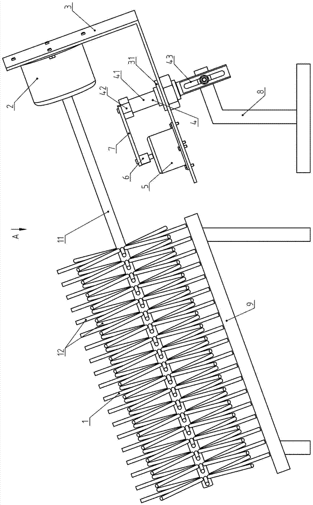
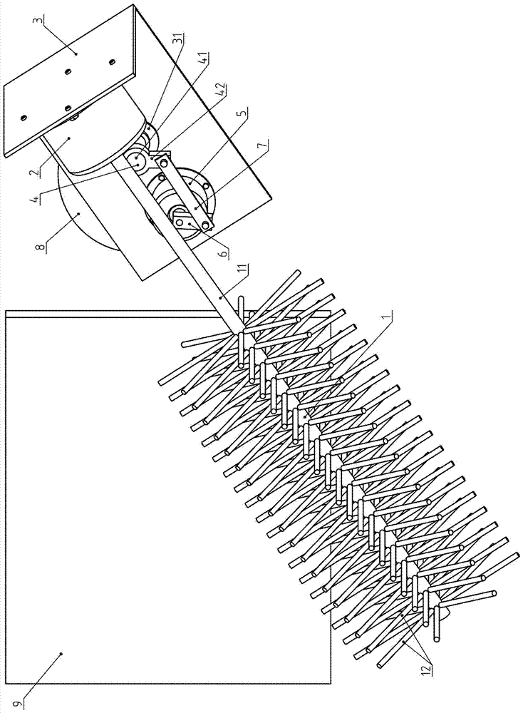
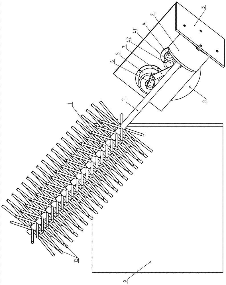
[0037] An automatic cleaning device for solar panels, including a brush 1, a rotating motor 2, a swing frame 3, a small crank 6, a small connecting rod 7, a base 8, a separate swing motor 5, and a rocker assembly 4,

[0038] The mounting base of the swing motor 5 is fixedly connected to the swing frame 3, the output shaft of the swing motor 5 is fixedly connected to the small crank 6, and the swing arm component 4 has a long sliding hole 43, which is connected to the swing arm component 4 and the base 8 through a threaded connector. , unscrew the threaded connector, you can adjust the relative position or angle between the two, and tighten it after adjusting properly; the swing arm assembly 4 and the swing frame 3 are connected by the swing frame hinge 31; the small crank 6 and the small connecting rod 7 ...

Embodiment 2

[0044] Example 2: see Figure 5 .

[0045] In this embodiment, four solar panels 9 are arranged side by side in a row, and a set of solar automatic cleaning equipment is installed on the north of each solar panel 9, and four sets are installed in total. The solar automatic cleaning equipment not only cleans a solar panel 9, but can clean two or three solar panels 9, can not protrude outside the solar panel when cleaning to any position, can improve utilization rate like this.

[0046] The solar panel is installed obliquely, the south-facing end is lower, and the north-facing end is higher. This embodiment is installed at the northern end of the solar panel 9 and does not occupy the positions on the east and west sides. There is no need to leave too much space between two side-by-side solar panels, which can make full use of the ground space and save land. One brush not only cleans one solar panel, but also cleans two or three adjacent solar panels, so the utilization rate of...

Embodiment 3

[0048] Embodiment 3: see Image 6 .

[0049] In this embodiment, a plurality of swing frames 3 are connected through a drive hinge 105 and a common connecting rod 104, the fixed flange of the common swing motor 102 is connected with the frame, the output shaft is fixedly connected with a large crank 106, and the common connecting rod 104 , big crank 106 are respectively connected with the two ends of big connecting rod 103 by hinges, big crank 106, big connecting rod 103, public connecting rod 104, rocking frame 3 form the crank linkage mechanism, when public rocking motor 102 rotates continuously, through The large connecting rod 103 and the common connecting rod 104 drive the four swing frames 3 to swing synchronously.

[0050] One common swing motor 102 in this embodiment drives four swing frames 3 to swing synchronously, the number of swing motors is reduced, the steps of installation and debugging are simplified, and the probability of failure is greatly reduced. At thi...


PUM


Abstract

The invention belongs to the technical field of solar power generation equipment, and relates to an automatic solar panel cleaning equipment, which includes a brush, a rotating motor, a swing frame, a crank link mechanism, a base, and a swing motor. The swing frame and the base are connected through a swing frame hinge, and the swing motor The installation base and the swing frame are fixedly connected, and the output shaft of the swing motor and the base are connected through a crank connecting rod; or the swing motor is fixedly connected to the frame, and the output shaft of the swing motor and the swing frame are connected through a crank connecting rod; The rotating motor is fixedly connected to the swing frame, and the brush rod is fixedly connected to the output shaft of the rotating motor; the brush rod is parallel to the solar panel, and the end of the bristles farther away from the brush rod brushes the surface of the solar panel. The invention has simple structure, convenient installation, low manufacturing, debugging and installation costs, is conducive to full utilization of ground space, and is conducive to standardization and serialization.

Description

technical field [0001] The invention belongs to the technical field of solar power generation equipment, and in particular relates to automatic cleaning equipment for solar panels. Background technique [0002] Solar panels, that is, solar panels, are devices that directly or indirectly convert solar radiation energy into electrical energy through photoelectric or photochemical effects by absorbing sunlight. They are the core components of solar power generation systems. Compared with ordinary batteries and rechargeable As far as batteries are concerned, solar cells are green products that are energy-saving and environmentally friendly. At present, the solar power generation system is a quite mature technology. [0003] Solar panels are usually installed outdoors in sunny locations. Usually, many groups of solar panels are installed collectively, or they can be installed separately. While solar panels receive sunlight, a lot of dust will fall on them. Dust hinders sunlight ...

Claims


Application Information

Patent Timeline
Patent Type & Authority Patents(China)
IPC IPC(8): B08B1/04H02S40/10
CPCH02S40/10B08B1/12B08B1/32Y02E10/50
Inventor 祝水云
Owner 贵阳渝冠技术服务中心
Learn More