
A kind of pcb board coding identification method

A PCB board and coding technology, which is applied in the field of coding, can solve problems such as the difficulty of complete preservation of PCB board-related information, affect identification, classification and use, and fail to meet market requirements, and achieve easy implementation, promotion of informatization, and reduction of PCB area. Effect

Inactive Publication Date: 2018-11-02
DONGGUAN ZHIJIE AUTOMATION MACHINE CO LTD
View PDF4 Cites 1 Cited by
  • Summary
  • Abstract
  • Description
  • Claims
  • Application Information

AI Technical Summary

Problems solved by technology

In the existing PCB board marking technology, because it is difficult to mark on the PCB board, the paper process card is usually used to record the relevant information of the PCB board, but in the process of corrosion and cleaning, it is easy to corrode or wash off the relevant information, As a result, it is difficult to completely preserve the relevant information of the PCB board, which affects the identification, classification and use, and cannot meet market requirements

Method used


Image

  • A kind of pcb board coding identification method
  • A kind of pcb board coding identification method
  • A kind of pcb board coding identification method

Examples


Embodiment 1

[0024] Such as figure 1 As shown, this embodiment proposes a method for coding and marking PCB boards. The method uses a punching device to process a plurality of through holes on the PCB board. The plurality of through holes are distributed in an array, and the distance between two adjacent through holes is Represents a single digit, and multiple digits are arranged in sequence to form a code. When decoding, image recognition equipment is used to collect multiple through holes, and the sequentially arranged digital code is obtained by measuring the distance between two adjacent through holes.

[0025] In this embodiment, a plurality of through holes are arranged in a one-dimensional array, and the through holes are circular holes, and the distance between the centers of two adjacent through holes minus the diameter of the through holes is used as the distance between two adjacent through holes. However, this is only a preferred embodiment of the present invention, and is not ...

Embodiment 2

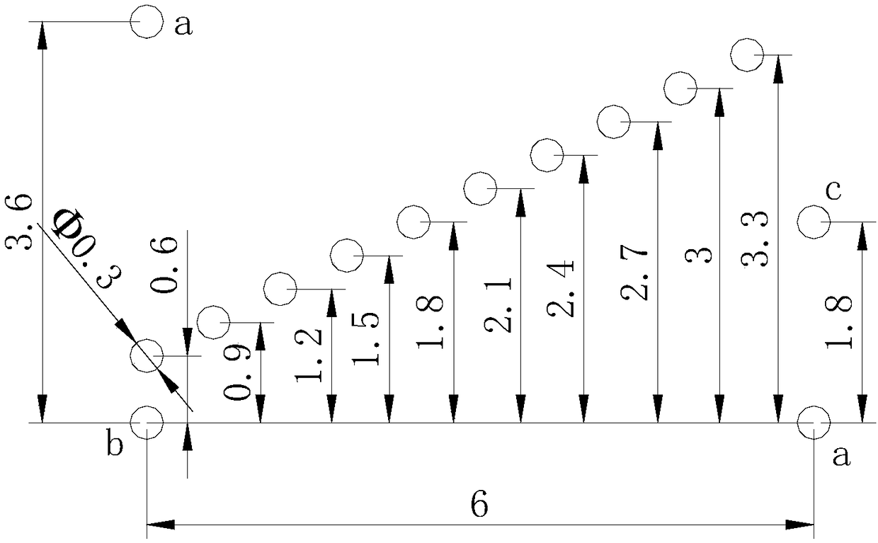
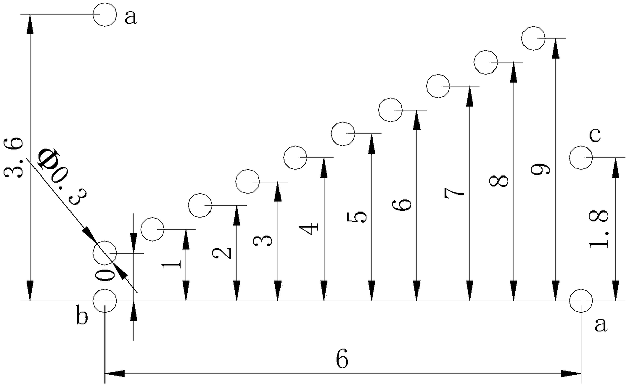
[0033] combine figure 2 and image 3 As shown, this embodiment proposes another array form, wherein a plurality of through holes are arranged in a two-dimensional array, each column in the two-dimensional array includes two through holes, and the distance between the two through holes Represents a single digit.

[0034] The code also includes an azimuth code, which is located before the valid code or on both sides of the valid code and the check code. For the two-dimensional hole distance marking method, three vertex holes can be punched on the edge of the first and last columns to mark the two-dimensional coding direction, and the right angle of the three holes is the starting point. For two-dimensional hole spacing coding, the two horizontal intervals represented by three vertex holes are 11 minimum units.

[0035] Please refer to figure 2 and image 3 , the application example is as follows: the diameter of the round hole is 0.3mm, the minimum spacing unit is 0.3mm, ...


PUM


Abstract

The invention discloses a PCB encoding identification method. A drilling device processes multiple through holes on a PCB. The multiple through holes are distributed in an array and the distance between every two adjacent through hole represents a one-bit number. The multiple bits of numbers are arranged successively to form a code. When decoding is carried out, an image recognition device acquires the multiple through holes and obtains the successively arranged number codes by measuring the distance between every two adjacent through hole. The method forms an encoding identifier by drilling the PCB so as to further record the correlative information of the PCB, thereby effectively prevent the correlative information from being corroded and cleaned.

Description

technical field [0001] The invention relates to a coding method, in particular to a method for coding and marking a PCB board. Background technique [0002] At present, the PCB industry has a large output and a wide variety of processing equipment. During production, a variety of equipment must be used for processing in sequence, resulting in a long production line, and the processing process will also involve multiple handling, corrosion and cleaning processes. With the development of the industry, the market has higher and higher requirements for the quality of PCB boards, and higher and higher requirements for the controllability of management. Especially in the era of Industry 4.0 and the Internet of Things, the reliable and unique identification of products is the key to all products. foundation of informatization. In the existing PCB board marking technology, because it is difficult to mark on the PCB board, the paper process card is usually used to record the relevan...

Claims


Application Information

Patent Timeline
Patent Type & Authority Patents(China)
IPC IPC(8): H05K1/02
CPCH05K1/0266H05K2201/09927
Inventor 李春庚
Owner DONGGUAN ZHIJIE AUTOMATION MACHINE CO LTD
Learn More