
Glass detection instrument with handle turntable, halo camera and nickel alloy ladder track corner splint

A glass detection and nickel alloy technology, applied in instruments, measuring devices, scientific instruments, etc., can solve the problems of operator injury, non-square, tape collapse, etc., to avoid splash injury, improve identification accuracy, and reduce labor intensity Effect

Inactive Publication Date: 2016-07-13
WENZHOU ECONOMIC TECH DEV ZONE BINHAI XIONGJIE ELECTROMECHANICAL RES & DEV STUDIO
View PDF3 Cites 2 Cited by
  • Summary
  • Abstract
  • Description
  • Claims
  • Application Information

AI Technical Summary

Problems solved by technology

Due to the diversity of automobile designs, the glass on the corresponding car is becoming more and more complex. The shape of the glass is often not square or rectangular, but parallelogram or trapezoidal glass can be found everywhere. In the past, there was no detection of this kind of irregular quadrilateral glass. Uniform fixtures can only use scotch tape or other methods to restrain the perimeter of the glass, or cover a layer of film on the tempered glass to prevent glass fragments from splashing
At the same time, the adhesive tape is also likely to be broken by the force of the tempered glass explosion, causing the operator to be injured. Therefore, it is very necessary to improve the test equipment for tempered glass fragments.

Method used


Image

  • Glass detection instrument with handle turntable, halo camera and nickel alloy ladder track corner splint
  • Glass detection instrument with handle turntable, halo camera and nickel alloy ladder track corner splint
  • Glass detection instrument with handle turntable, halo camera and nickel alloy ladder track corner splint

Examples


Embodiment Construction

[0056] Describe the present invention in detail below in conjunction with accompanying drawing and specific embodiment:

[0057] figure 1 In the test turntable 190, the stepped rail splint assembly 500 is removed.

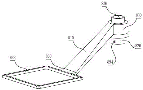
[0058] Figure 13 Among them, the ladder track splint assembly 500 is placed on the test turntable 190, and the trapezoidal glass plate 600 is fixed. The screw lifting camera group 900 does not work when it is lifted, the moving halo 800 does not work when it is moved outward, and the rotary impactor 590 is located directly above the trapezoidal glass plate 600. working status.

[0059] Figure 14 Among them, the ladder track splint assembly 500 is placed on the test turntable 190, and the trapezoidal glass plate 600 is fixed, the rotary impactor 590 is transferred out of the test turntable 190 and is in a non-working state, the screw lifting camera group 900 is in a working state when it is lowered, and the moving halo 800 is located in the trapezoidal The gla...


PUM

PropertyMeasurementUnit
thicknessaaaaaaaaaa
heightaaaaaaaaaa
widthaaaaaaaaaa

Abstract

The invention relates to a tempered glass test detection instrument. The improvement of a glass detection instrument with a handle turntable, a halo camera and a nickel alloy ladder track corner splint is as follows: a platen handle is arranged on a rear-end vertical surface of a test turntable; two bent arc ends of the platen handle are arranged as handle heads; the handle heads at the two bent arc ends are fixedly arranged on the rear-end vertical surface of the test turntable; two horizontal rods are in sliding fit with horizontal shooting slide blocks; a square shooting rod is fixed between the two horizontal shooting slide blocks; a screw lifting camera unit is arranged on the square shooting rod; a square fluorescent tube is arranged on a moveable halo; a ladder track splint component is fixedly arranged on the upper surface of the test turntable; a broken glass guide is fixedly arranged between a turntable support base and a lock pin support base as well as the upper surface of a supporting lateral plate; a rotatable impacting device is slidably and fixedly arranged on a horizontal impacting rod; the ladder track splint component is applied to a direct turning structure of the platen handle of the test turntable, so that the fixing for quadrilateral glass at different included angles can be realized.

Description

technical field [0001] The invention relates to a tempered glass test and inspection device, in particular to a device for inspecting plywood glass with a halo-assisted camera instead of a manual-operated handle turntable halo camera for nickel alloy ladder track corners. Background technique [0002] Since Gordon GaileG published the article "Automated Glass Fragmentation Analysis" in 1996, the detection algorithm of glass fragments has been discussed. Light sources were applied at different angles, and an original digital image of the shadow of the crack line of the debris was collected. In this way, due to the use of light sources at different angles, the two images collected must be different. In one of the images, the position of the inconspicuous seam line due to lighting may be more obvious in the other image. Therefore, when the two images are combined at an appropriate time, the discontinuous phenomenon of the seam line will be improved. 2 Image Segmentation Al...

Claims


Application Information

Patent Timeline
Patent Type & Authority Applications(China)
IPC IPC(8): G01N21/01G01N21/958
CPCG01N21/01G01N21/958
Inventor 张志雄
Owner WENZHOU ECONOMIC TECH DEV ZONE BINHAI XIONGJIE ELECTROMECHANICAL RES & DEV STUDIO
Learn More