
Thermal power plant heat network energy saving system and method

A technology for energy-saving systems and thermal power plants, applied in heating systems, hot water central heating systems, heating methods, etc., can solve problems such as the difficulty of significantly reducing the energy consumption of heating network circulation pumps, so as to increase the revenue of thermal power enterprises and increase the temperature of water supply , the effect of reducing power consumption

Inactive Publication Date: 2016-07-13
HUADIAN ELECTRIC POWER SCI INST CO LTD
View PDF6 Cites 3 Cited by
  • Summary
  • Abstract
  • Description
  • Claims
  • Application Information

AI Technical Summary

Problems solved by technology

[0005] Although there are also some thermal power plant heat network energy-saving systems and methods, such as the Chinese patent whose publication date is April 23, 2014, and whose publication number is CN103742964A, a waste heat recovery thermal power plant energy storage method and its system are disclosed; and the publication date is On October 3, 2012, a Chinese patent with the publication number CN102705020A disclosed a combined heat and power system and a heating method; however, it is difficult for existing technologies of this type to significantly reduce the energy consumption of the heating network circulation pump

Method used


Image

  • Thermal power plant heat network energy saving system and method

Examples


Embodiment Construction

[0017] The present invention will be further described in detail below in conjunction with the accompanying drawings and examples. The following examples are explanations of the present invention and the present invention is not limited to the following examples.

[0018] Example.

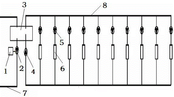
[0019] see figure 1 , the thermal power plant heat network energy-saving system in this embodiment includes a heat source side pipeline 7, a heat network heater 3, a primary heat network circulating water pump frequency converter 1 located on the heat source side, a primary heat network circulating water pump 2 located on the heat source side, and a user The secondary heating network circulating water pump 4 on the side, the booster pump 5 for the heat user, the temperature instrument 6 at the heat user and the pipeline 8 on the user side.

[0020] The primary heating network circulating water pump 2 in this embodiment not only undertakes the water circulation function inside the heat source, but ...


PUM


Abstract

The invention relates to a thermal power plant heat network energy saving system and method, and belongs to a firepower coal fired power generation heat supply unit. In the prior art, the energy consumption of a thermal network circulation pump is difficult to be obviously reduced. The system comprises a heat source side pipeline, and is characterized by also comprising a heat network heater, a primary heat network circulation water pump frequency converter, a primary heat network circulation water pump, a secondary heat network circulation water pump, a heat user pressure boosting pump, a heat user part temperature instrument and a user side pipeline, wherein the primary heat network circulation water pump is arranged on the heat source side pipeline; the secondary heat network circulation water pump, the heat user pressure boosting pump and the heat user part temperature instrument are arranged on the user side pipeline; the heat source side pipeline and the user side pipeline are connected with the heat network heater. The method provided by the invention comprises the following steps that during the system operation, the water supply temperature is raised; the primary heat network water supply and water return temperature differences are increased; the primary heat network circulation water flow rate is further reduced. The system and the method have the advantages that the energy consumption of the heat network circulation pump can be obviously reduced; the integral efficiency of a thermal power plant unit and the profits of thermoelectric enterprises are improved.

Description

technical field [0001] The invention relates to an energy-saving system and method for a heating network of a thermal power plant, which belongs to thermal coal-fired power generation and heat supply units. Background technique [0002] In recent years, environmental pollution has been serious, environmental risks have been high, and ecological losses have been great. The state requires the improvement of environmental quality to be the core, to fight a protracted and tough battle for environmental protection, and to reduce emissions as the top priority. The "Coal Power Energy Conservation and Emission Reduction Upgrading and Transformation Action Plan" (Fagai Energy No. 20142093) requires that the energy conservation transformation of coal power be done effectively, and the promotion of advanced coal power energy saving technologies and methods be accelerated. [0003] Due to the prominent energy problem, energy is an important restrictive factor for my country's economic ...

Claims


Application Information

Patent Timeline
IPC IPC(8): F24D3/02F01K17/02
CPCF01K17/02F24D3/02Y02E20/14Y02P80/10
Inventor 张士龙郭佳雷庞乐邴汉昆
Owner HUADIAN ELECTRIC POWER SCI INST CO LTD
Learn More