
Active labyrinth seal structure

A labyrinth sealing, active technology, applied in the direction of engine sealing, engine components, mechanical equipment, etc., can solve the problems of gas leakage, and achieve the effect of enhancing the sealing effect and inhibiting gas leakage.

Active Publication Date: 2016-07-13
ESURGING TIANJIN TECH CO LTD
View PDF8 Cites 6 Cited by
  • Summary
  • Abstract
  • Description
  • Claims
  • Application Information

AI Technical Summary

Problems solved by technology

[0003] In view of this, the present invention aims to propose an active labyrinth sealing structure to solve the problem of gas leakage using traditional sealing structures

Method used


Image

  • Active labyrinth seal structure
  • Active labyrinth seal structure
  • Active labyrinth seal structure

Examples


Embodiment 1

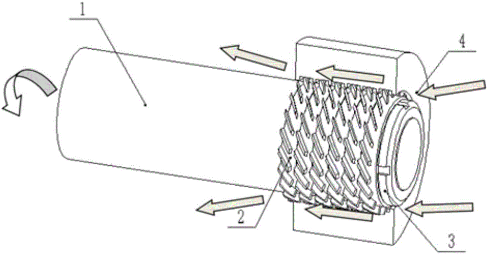
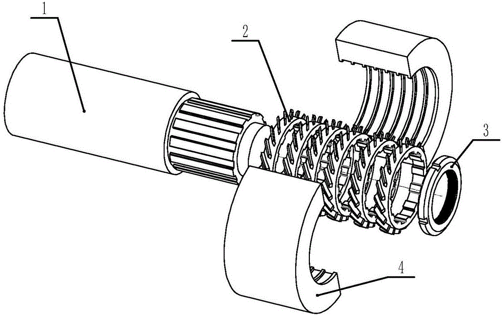
[0026] Such as figure 1 As shown, the present invention is an active labyrinth seal structure, including a rotor 1, a blade sealing ring 2, a semicircular sealing sheath 4, and a lock nut 3 at the shaft end. The blade seal ring 2 is fastened to the rotor 1 through a spline connection, and the number of blade seal rings is superimposed according to the need. The shaft end of the rotor 1 is fastened with a lock nut 3, and then two semicircular seal sheaths 4 are buckled on the blade seal. On the ring, the rectangular teeth on the sealing sheath 4 are used for crossing the blades. When the rotor 1 rotates, it drives the blade sealing ring to rotate, and the blades on the blade sealing ring 2 can form active directional airflow in the sealing channel.

[0027] The left side of the seal is the high-pressure side, and the right side is the low-pressure side. Normally, the gas will flow from the high-pressure side to the low-pressure side, resulting in pressure loss on the high-press...

Embodiment 2

[0031] Such as Figure 4 , 5 As shown, the gas enters from the air inlet 41 on the sealing sheath 4, because the blade sealing ring 2 and the reverse blade sealing ring 5 have a separation effect on the gas entering the sealing gap, and the sealing effect is achieved. When the rotor rotates On the contrary, the positions of the vane sealing ring 2 and the reverse vane sealing ring 5 can be exchanged.


PUM


Abstract

The invention provides an active labyrinth seal structure. The active labyrinth seal structure comprises a rotor, blade seal rings, seal jackets and a locking nut, wherein the blade seal rings are fastened with the rotor through spline joints; the number of blade seal rings can be increased as needed; a shaft end of the rotor is fastened by using the locking nut; the two semi-round seal jackets are fastened on the blade seal rings; rectangular teeth on the seal jackets are crossed with blades; and when rotating, the rotor drives the blade seal rings to rotate, and the blades on the seal rings can form active reverse air flow in a seal channel, so that the air leakage can be effectively inhibited. The active labyrinth seal structure is simple in structure and better in seal effect.

Description

technical field [0001] The invention belongs to the field of sealing devices for rotating mechanical equipment, and in particular relates to an active labyrinth sealing structure. Background technique [0002] The shaft sealing device is an indispensable sealing device in rotating machinery, and usually adopts a labyrinth sealing structure. In rotating mechanical equipment, because the rotor rotates at high speed and the stator is stationary, there will be a gap between the two. When there is a gas pressure difference between the inside and outside of the equipment, it will cause the gas to flow in the seal. Using the traditional seal structure, Gas leaks are bound to occur. Contents of the invention [0003] In view of this, the present invention aims to propose an active labyrinth sealing structure to solve the problem of gas leakage using traditional sealing structures. [0004] In order to achieve the above object, technical solution of the present invention is achie...

Claims


Application Information

Patent Timeline
Patent Type & Authority Applications(China)
IPC IPC(8): F16J15/447
CPCF16J15/4472F16J15/4476
Inventor 刘志忠沙宏磊俞天野何毅张志华孙吉松王胜迎沙佩亮王向荣潘少杰
Owner ESURGING TIANJIN TECH CO LTD
Learn More