
Gear milling clamp for bevel gear

A bevel gear and tooth milling technology, which is applied to gear tooth manufacturing devices, belts/chains/gears, gear teeth, etc., can solve the problems of complex structure and high manufacturing cost of bevel gear fixtures, and achieve convenient and fast clamping and low manufacturing cost , The effect of simple fixture structure

Inactive Publication Date: 2016-07-13
CHONGQING TAIJING PACKAGING PROD
View PDF0 Cites 0 Cited by
  • Summary
  • Abstract
  • Description
  • Claims
  • Application Information

AI Technical Summary

Problems solved by technology

[0003] In view of this, the object of the present invention is to provide a bevel gear milling fixture to solve the problems of complex structure and high manufacturing cost of the existing bevel gear fixture

Method used


Image

  • Gear milling clamp for bevel gear

Examples


Embodiment Construction

[0013] The present invention will be further described below in conjunction with the accompanying drawings and embodiments.

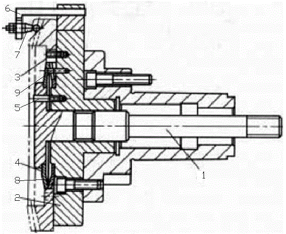
[0014] As shown in the figure, the bevel gear milling fixture of this embodiment includes a pull rod 1 and a positioning plate 2 that is coaxially sleeved on the pull rod. The positioning plate and the pull rod slide in the axial direction. There is a chamfered positioning pin 3, and a centering shaft section is integrally provided on the other end surface of the positioning plate;

[0015] The end of the pull rod is integrally provided with a pressure plate, and the end of the pressure plate close to the positioning plate is provided with an annular step, and the first disc spring 4 is sleeved on the annular step;

[0016] It also includes a first circumferential positioning pin 5 arranged on the positioning plate and slidingly fitted with the pressure plate in the axial direction.

[0017] The bevel gear milling jig of this embodiment locates the cen...


PUM


Abstract

The invention discloses a gear milling clamp for a bevel gear. The gear milling clamp comprises a pull rod and a positioning plate coaxially nested on the pull rod, wherein the positioning plate and the pull rod are glidingly matched in the axial direction, an edge-chamfered positioning pin is arranged on the end surface of one side of the positioning plate, and a spigot shaft section is integrally arranged on the end surface of the other side of the positioning plate; a press plate is integrally arranged at the end part of the pull rod, and an annular step is arranged at one end, close to the positioning plate, of the press plate and sleeved with a first belleville spring; the gear milling clamp further comprises a first circumferential positioning pin which is arranged on the positioning plate and is glidingly matched with the press plate in the axial direction. According to the gear milling clamp for the bevel gear, during rough machining of a gear, the center position of the gear is positioned through matching of the belleville spring and an inner hole of the gear, the circumferential position of the gear is positioned through the edge-chamfered positioning pin, the diameter of the belleville spring is increased by pressing the belleville spring by the aid of the pressing plate, accordingly, the belleville spring is expanded to fix the gear, the assembly and clamping are convenient and rapid, and besides, the clamp is simple in structure and low in manufacturing cost.

Description

technical field [0001] The invention relates to a fixture, in particular to a bevel gear milling fixture. Background technique [0002] In the gear milling process of bevel gears, it is necessary to use fixtures to position the workpiece. The gear milling fixtures in the prior art have complex structures and high manufacturing costs. Contents of the invention [0003] In view of this, the purpose of the present invention is to provide a bevel gear milling fixture to solve the problems of the existing bevel gear fixtures with complex structure and high manufacturing cost. [0004] The bevel gear milling jig of the present invention comprises a pull rod and a positioning plate coaxially sheathed on the pull rod, the positioning plate and the pull rod are axially slidably matched, and one end surface of the positioning plate is provided with a chamfering positioning pin, and the positioning plate A centering shaft section is integrally provided on the other end face of the ...

Claims


Application Information

Patent Timeline
IPC IPC(8): B23F23/06
Inventor 冉华刚
Owner CHONGQING TAIJING PACKAGING PROD
Learn More