Optical concentration sensor protection cover and optical concentration testing device
An optical concentration and sensor technology, applied in the field of sensors, can solve the problems of inability to eliminate the bubbles of the solution to be tested in advance, low reliability, affecting the accuracy of the urea concentration test, etc., and achieve the effects of eliminating bubbles, prolonging service life and improving accuracy.
- Summary
- Abstract
- Description
- Claims
- Application Information
AI Technical Summary
Problems solved by technology
Method used
Image

Examples
Embodiment 1
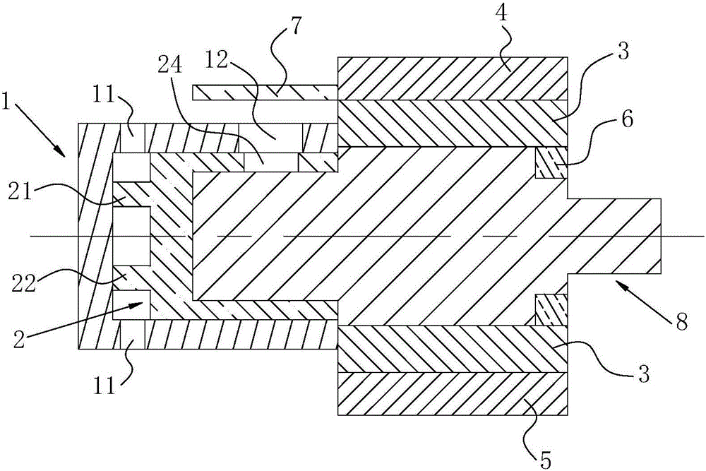
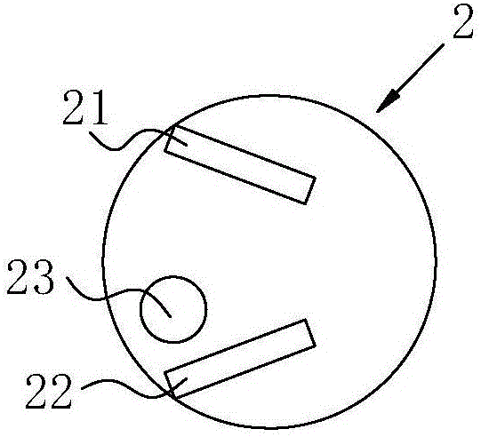
[0071] Such as Figure 1 to Figure 3 As shown, a protective cover for an optical density sensor includes an outer cover 1 and a bubble barrier 2, and the bubble barrier 2 is embedded in the inner side of the outer cover 1; it also includes a fixed middle frame 3, a fixed upper bracket 4, Fix the lower bracket 5 and the fixing ring 6, the outer cover 1 and the air bubble shield 2 are installed on one end of the fixed middle frame 3, the fixed ring 6 is installed on the other end of the fixed middle frame 3, and the fixed The upper bracket 4 and the fixed lower bracket 5 are sleeved on the outside of the fixed middle frame 3 . The inner space of the bubble shield 2 and the fixed middle frame 3 forms a test area for the solution to be tested.
[0072] Wherein, the outer cover 1 is provided with a convection hole 11; the bubble shield 2 is provided with a liquid inlet 23; a barrier is arranged between the convection hole 11 and the liquid inlet 23, and the solution to be tested ...
Embodiment 2
[0082] Such as Figure 4 to Figure 6 As shown, a protective cover for an optical density sensor includes an outer cover 1 and a bubble barrier 2, and the bubble barrier 2 is embedded in the inner side of the outer cover 1; it also includes a fixed middle frame 3, a fixed upper bracket 4, Fix the lower bracket 5 and the fixing ring 6, the outer cover 1 and the air bubble shield 2 are installed on one end of the fixed middle frame 3, the fixed ring 6 is installed on the other end of the fixed middle frame 3, and the fixed The upper bracket 4 and the fixed lower bracket 5 are sleeved on the outside of the fixed middle frame 3 . The inner space of the bubble shield 2 and the fixed middle frame 3 forms a test area for the solution to be tested.
[0083] Wherein, the outer cover 1 is provided with a convection hole 11; the bubble shield 2 is provided with a liquid inlet 23; a barrier is arranged between the convection hole 11 and the liquid inlet 23, and the solution to be tested ...
Embodiment 3
[0093] Such as Figure 7 to Figure 9 As shown, a protective cover for an optical density sensor includes an outer cover 1 and a bubble barrier 2, and the bubble barrier 2 is embedded in the inner side of the outer cover 1; it also includes a fixed middle frame 3, a fixed upper bracket 4, Fix the lower bracket 5 and the fixing ring 6, the outer cover 1 and the air bubble shield 2 are installed on one end of the fixed middle frame 3, the fixed ring 6 is installed on the other end of the fixed middle frame 3, and the fixed The upper bracket 4 and the fixed lower bracket 5 are sleeved on the outside of the fixed middle frame 3 . The inner space of the bubble shield 2 and the fixed middle frame 3 forms a test area for the solution to be tested.
[0094] Wherein, the outer cover 1 is provided with a convection hole 11; the bubble shield 2 is provided with a liquid inlet 23; a barrier is arranged between the convection hole 11 and the liquid inlet 23, and the solution to be tested ...
PUM
 Abstract
Description
Claims
Application Information
 - R&D
- Intellectual Property
- Life Sciences
- Materials
- Tech Scout
- Unparalleled Data Quality
- Higher Quality Content
- 60% Fewer Hallucinations
Browse by: Latest US Patents, China's latest patents, Technical Efficacy Thesaurus, Application Domain, Technology Topic, Popular Technical Reports.
© 2025 PatSnap. All rights reserved.Legal|Privacy policy|Modern Slavery Act Transparency Statement|Sitemap|About US| Contact US: help@patsnap.com