
Pneumatic lifting device of shooting barrel of core shooting machine

A technology of pneumatic lifting and core shooting machine, applied in the field of foundry sand core modeling, can solve the problems of guide post damage, equipment damage, guide post fracture, etc., and achieve the effect of avoiding movement deviation and avoiding damage

Active Publication Date: 2016-07-06
CHONGQING HONGQI CYLINDER HEAD MFG
View PDF5 Cites 1 Cited by
  • Summary
  • Abstract
  • Description
  • Claims
  • Application Information

AI Technical Summary

Problems solved by technology

[0004] In the prior art, there is a commonly used shooting tube lifting device, which includes a shooting tube guide box, and a guide post sleeve is provided at the bottom of the shooting tube guide box, and guide posts are slidably connected to the inside of the guide post cover; Press down the oil cylinder, the spring is connected to the press down oil cylinder, and the end of the spring away from the press down oil cylinder is connected with the spring cover. When the barrel needs to rise, the press down oil cylinder is retracted. Under the action, it will push the barrel to rise. Since the spring itself is soft, the force of the spring is unstable. During the rising process, the barrel will swing, so that the guide post will shake in the guide post sleeve, and the impact will make it The guide column is worn out; when the barrel needs to be in a lowered state, the down-pressing cylinder is pressed down. Due to the large force of the down-pressing cylinder, it will overcome the spring tension and force the barrel to drop in place, but when the barrel is down , Sometimes the guide post and the guide post sleeve in the barrel guide box are not fully matched, resulting in increased resistance when descending, but the strong force of the oil cylinder will still press down the barrel guide box, so that the barrel will drop into place. At this time, the guide post will be damaged or even broken due to forced pressing down, resulting in equipment damage.

Method used


Image

  • Pneumatic lifting device of shooting barrel of core shooting machine

Examples


Embodiment Construction

[0014] The present invention will be described in further detail below by means of specific embodiments:

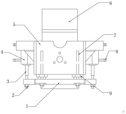
[0015] The reference signs in the accompanying drawings of the specification include: barrel connecting plate 1, lock nut 2, cylinder connecting head 3, lifting cylinder 4, T-shaped barrel connecting frame 5, barrel 6, guide post 7, magnetic induction switch 8, Guide post cover 9.

[0016] The embodiment is basically as attached figure 1 Shown:

[0017] The cylinder pneumatic lifting device of the core shooter in this solution includes a cylinder connection plate 1, and four first through holes are opened in the middle of the cylinder connection plate 1, and the first through holes are arranged in a rectangular array on the cylinder connection plate 1 Arranged, each first through hole is interference-fit connected with a guide post 7; a T-shaped connecting plate is arranged above the barrel connecting plate 1, and the T-shaped connecting plate includes a transverse part...


PUM


Abstract

The invention discloses a pneumatic lifting device of a shooting barrel of a core shooting machine. The pneumatic lifting device comprises a shooting barrel connection plate, wherein a plurality of first through holes are formed in the middle of the shooting barrel connection plate; the first through holes are internally fixedly connected with guide columns. The pneumatic lifting device further comprises an air cylinder, wherein the air cylinder comprises an air cylinder body and an air cylinder connector; the air cylinder connector is connected with the shooting barrel connection plate through a locking nut; the air cylinder body is connected with a T-shaped shooting barrel connection frame; a plurality of vertical guide holes, which are in slide match with the guide columns, are formed in one side, close to the shooting barrel connection plate, of the T-shaped shooting barrel connection frame; and the T-shaped shooting barrel connection frame is internally provided with the shooting barrel. Compared with the prior art, the air cylinder moves up and down so that the ascending and descending process of the shooting barrel is stable; and a stress working condition of the shooting barrel connection frame is improved and the service life of the equipment is prolonged.

Description

technical field [0001] The invention belongs to the field of casting sand core modeling. Background technique [0002] The core shooter is widely used in the foundry industry. The sand cores made by the core shooter are accurate in size and smooth in surface. The working principle of the core shooting machine is to inject the mixture with liquid or solid thermosetting resin as the binder into the heated core box. The mixture is heated and hardened in the core box and then taken out to form a smooth surface and precise size Finished high-quality sand cores. [0003] Because the use of core shooter molding can save high labor costs, it is widely used. The core shooting machine is mainly composed of four parts, which are the column parts, the sand shooting device, the formwork part and the base. Composed of beams and columns; the sand-shooting device includes sand cylinders, air valves, sand cylinder frames, injection heads, sand-shooting plates and other components; the for...

Claims


Application Information

Patent Timeline
IPC IPC(8): B22C15/23
CPCB22C15/23
Inventor 陈建军黄文礼
Owner CHONGQING HONGQI CYLINDER HEAD MFG
Learn More