
Sheet Metal Cutting Equipment

A technology for cutting equipment and metal plates, applied in metal sawing equipment, metal processing equipment, sawing machine devices, etc., can solve the problems of difficult to completely remove burrs, time and cost consumption, etc., to save cost and time, improve cutting quality, The effect of improving quality

Inactive Publication Date: 2018-06-08
POHANG IRON & STEEL CO LTD +1
View PDF6 Cites 2 Cited by
  • Summary
  • Abstract
  • Description
  • Claims
  • Application Information

AI Technical Summary

Problems solved by technology

However, such a secondary process results in additional time and cost consumption, and it may still be difficult to completely remove the burrs even if such a secondary process is implemented

Method used


Image

  • Sheet Metal Cutting Equipment
  • Sheet Metal Cutting Equipment
  • Sheet Metal Cutting Equipment

Examples


Embodiment Construction

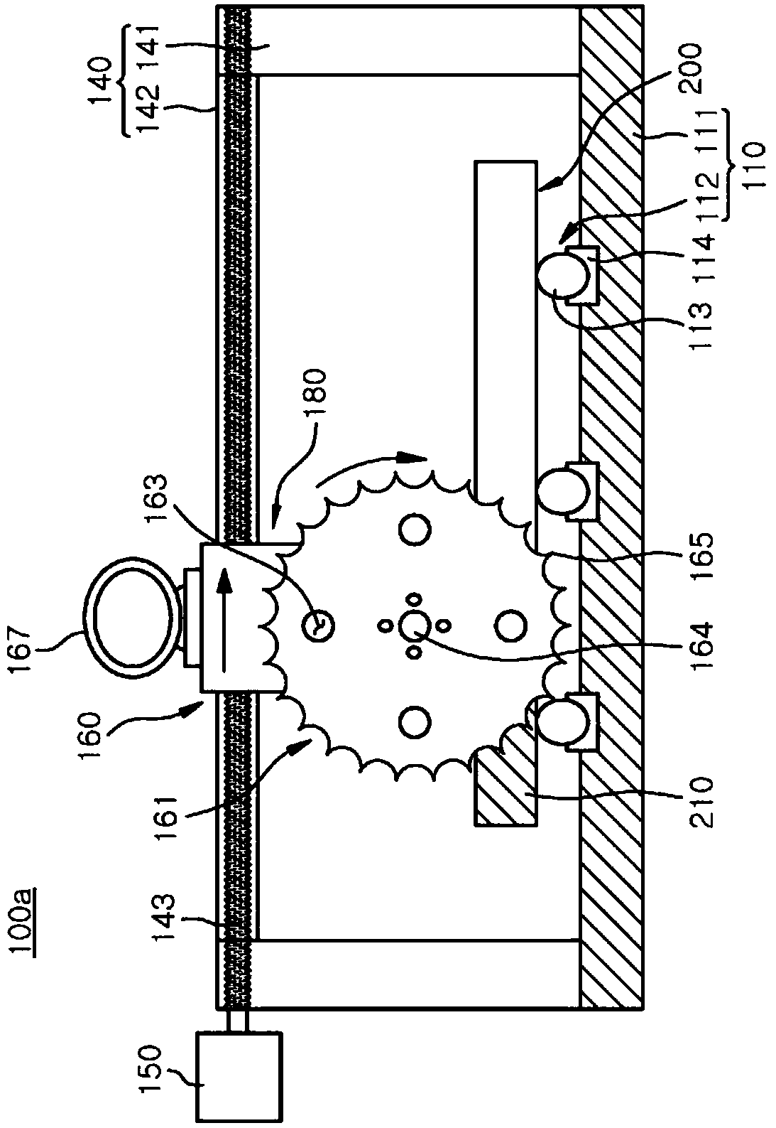
[0067] figure 1 is a perspective view illustrating a sheet metal cutting apparatus 100a of an exemplary embodiment of the present disclosure, and figure 2 is schematically shown figure 1 A frontal cross-sectional view of the sheet metal cutting apparatus 100a shown in . image 3 is schematically shown figure 1 A side cross-sectional view of the sheet metal cutting apparatus 100a shown in . In the following, reference will be made to Figure 1 to Figure 3 A sheet metal cutting apparatus 100a of an exemplary embodiment is described.

[0068] Such as Figure 1 to Figure 3 As shown in , the metal plate cutting apparatus 100 a of the exemplary embodiment may include a table 110 , a frame unit 140 and a cutting unit 160 . The cutting unit 160 may include: a first driving unit 167; a saw unit 161 having a rotation shaft 164 disposed above the metal plate 200 placed on the upper surface of the table 110; and a power transmission unit 180, It is configured to transmit drive pow...


PUM

PropertyMeasurementUnit
thicknessaaaaaaaaaa
strengthaaaaaaaaaa
lengthaaaaaaaaaa

Abstract

The present invention relates to a metal plate cutting device and, more specifically, to a metal plate cutting device which has an easy cutting process since a rotary shaft of a saw blade part is positioned above a metal plate. The metal plate cutting device, according to one embodiment of the present invention, comprises: a support part having a metal plate disposed a top surface thereof; a frame part which is supported by the top surface of the support part; and a cutting part capable of moving along the frame part, wherein the cutting part includes a saw blade part for cutting the metal plate by rotating a rotary shaft which is positioned above the metal plate.

Description

technical field [0001] The present disclosure relates to a sheet metal cutting apparatus, and more particularly, to a sheet metal cutting apparatus configured to easily cut a sheet metal with a saw unit whose shaft is arranged on a metal above the board. [0002] Furthermore, the present disclosure relates to a metal plate cutting device including a metal plate conveying device configured to accurately convey the metal plate to a cutting position regardless of the thickness of the metal plate . [0003] Furthermore, the present disclosure relates to a sheet metal cutting apparatus configured to precisely machine very thick sheet metal with less vibration and with low dimensional deviations. Background technique [0004] In a related art, a gas torch is used to cut sheet metal, particularly thick sheet metal. When cutting a metal plate with a gas torch, a part of the metal plate heated with the gas torch reacts with oxygen and melts due to the heat of oxidation, and the me...

Claims


Application Information

Patent Timeline
Patent Type & Authority Patents(China)
IPC IPC(8): B23D45/02B23D47/08
CPCB23D45/021B23D47/025B23D47/08
Inventor 文昌晧李圣珍林承昊金镇浩申健芦庚禾崔刚赫金英贤金秉辰金弘基南龙镐李明熙朴峰熙李东奎
Owner POHANG IRON & STEEL CO LTD
Learn More