Following method and device of unmanned aerial vehicle and wearable equipment
A technology for unmanned aerial vehicles and equipment, which is applied in the field of human-computer interaction and can solve the problems of inability to achieve autonomous following of unmanned aerial vehicles and poor user experience.
- Summary
- Abstract
- Description
- Claims
- Application Information
AI Technical Summary
Problems solved by technology
Method used
Image
Examples
Embodiment 1
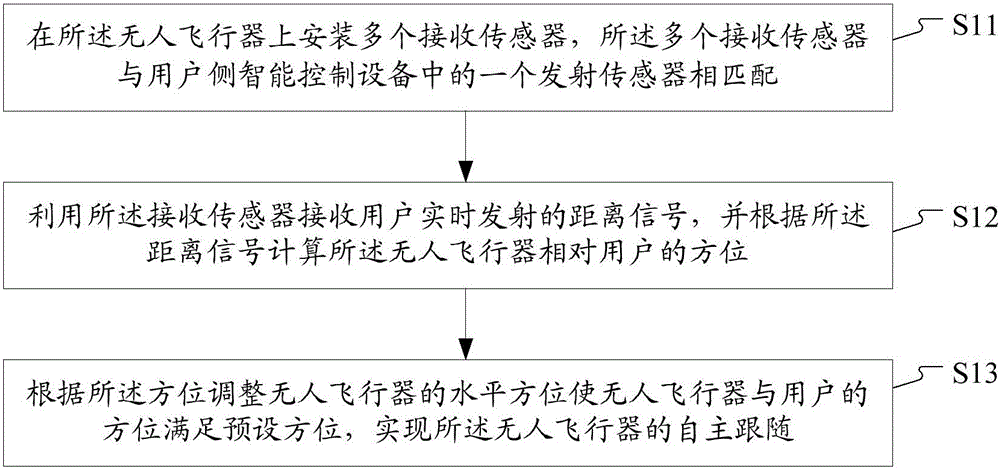
[0045] figure 1 It is a schematic flow chart of a method for following an unmanned aerial vehicle according to an embodiment of the present invention, see figure 1 , the following method of the unmanned aerial vehicle comprises the following steps:
[0046] Step S11, installing multiple receiving sensors on the unmanned aerial vehicle, the multiple receiving sensors are matched with one transmitting sensor in the user-side intelligent control device;
[0047] The matching here at least includes: the type of the receiving sensor matches the type of the transmitting sensor. For example, when the receiving sensor is an ultrasonic sensor, the transmitting sensor also adopts an ultrasonic sensor, that is, it is ensured that the transmitting sensor and the receiving sensor are of the same type. And, identity matching between the receiving sensor and the transmitting sensor. For example, during the initialization process, the receiving sensor receives the pairing connection request ...
Embodiment 2
[0055] Ultrasonic signals have advantages in near-field signal transmission, less affected by environmental and lighting factors, stable transmission, strong anti-interference ability, and are an ideal medium for autonomous tracking of unmanned aerial vehicles. Therefore, in this embodiment, taking the receiving sensor as an ultrasonic receiving sensor and the transmitting sensor as an example of an ultrasonic transmitting sensor, the positioning of the user by the unmanned aerial vehicle in the following method of the unmanned aerial vehicle is mainly explained. For other contents, refer to other implementations of the present invention. Example description.
[0056] In this embodiment, at least three ultrasonic sensors are installed on the UAV, and the orientation between the user and the UAV is calculated according to the ultrasonic signals emitted by the ultrasonic transmitting sensor installed in the intelligent control device on the user side.
[0057] The principle of t...
Embodiment 3
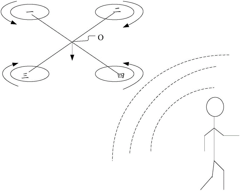
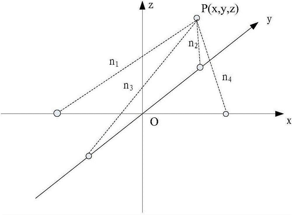
[0062] figure 2 It is a schematic diagram of the relative orientation between the unmanned aerial vehicle and the user according to an embodiment of the present invention, image 3 It is a schematic diagram of a spatial Cartesian coordinate system constructed based on the azimuth relationship between an unmanned aerial vehicle and a user in an embodiment of the present invention, combined with figure 2 and image 3 , this embodiment illustrates the process of calculating the orientation of the UAV relative to the user.
[0063] Depend on figure 2 It can be seen that the unmanned aerial vehicle in this embodiment is a quadrotor unmanned aerial vehicle. The quadrotor aircraft changes the rotational speed of the rotor by adjusting the rotational speed of the four motors to achieve changes in flight speed and lift, thereby controlling the attitude and position of the unmanned aerial vehicle. The quadrotor aircraft is equipped with four ultrasonic signal receiving sensors, th...
PUM
 Abstract
Description
Claims
Application Information
 - R&D Engineer
- R&D Manager
- IP Professional
- Industry Leading Data Capabilities
- Powerful AI technology
- Patent DNA Extraction
Browse by: Latest US Patents, China's latest patents, Technical Efficacy Thesaurus, Application Domain, Technology Topic, Popular Technical Reports.
© 2024 PatSnap. All rights reserved.Legal|Privacy policy|Modern Slavery Act Transparency Statement|Sitemap|About US| Contact US: help@patsnap.com


