Helical ribbon vacuum dryer and working method thereof

A technology of vacuum dryers and ribbons, which is applied to non-progressive dryers, dryers, and drying solid materials, etc., can solve the problems of uneven heating, limited stirring, and low drying efficiency, so as to avoid material agglomeration , Facilitate fast drying and fast heating effect

Inactive Publication Date: 2016-06-29
陆文光
View PDF6 Cites 3 Cited by
  • Summary
  • Abstract
  • Description
  • Claims
  • Application Information

AI Technical Summary

Problems solved by technology

As the application publication number is CN101571345A, the single screw ribbon and the scraper used in the mixing dryer stir and mix the material. Because the frame-shaped scraper has a large volume, the single screw ribbon and the scraper act on the material. During the process, it is easy to make the material in the cylinder move together with the frame-shaped scraper and the single screw belt. The moving material is like a whole, causing the material to agglomerate, and a large amount of energy consumption is used for the circular motion of the whole material. The drying efficiency provided is low and the stirring effect on the material is limited. In addition, the solution only has the jacketed cylinder to heat the material, and the heating area is small, the heating is uneven and the process is slow.

Method used


Image

  • Helical ribbon vacuum dryer and working method thereof
  • Helical ribbon vacuum dryer and working method thereof
  • Helical ribbon vacuum dryer and working method thereof

Examples


Embodiment Construction

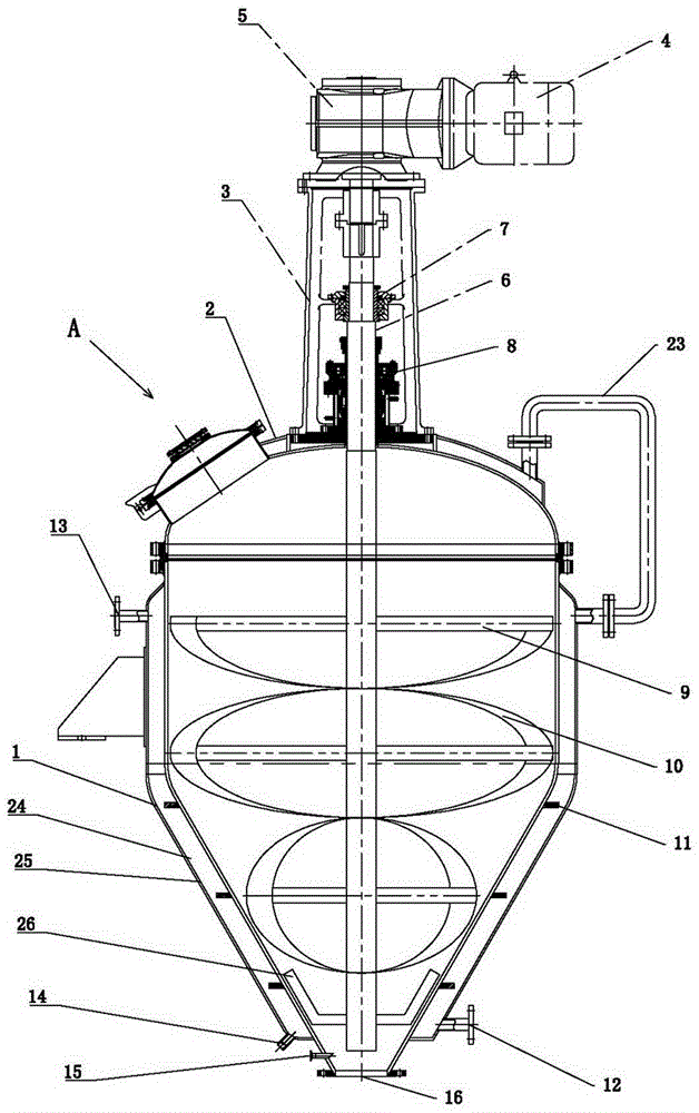
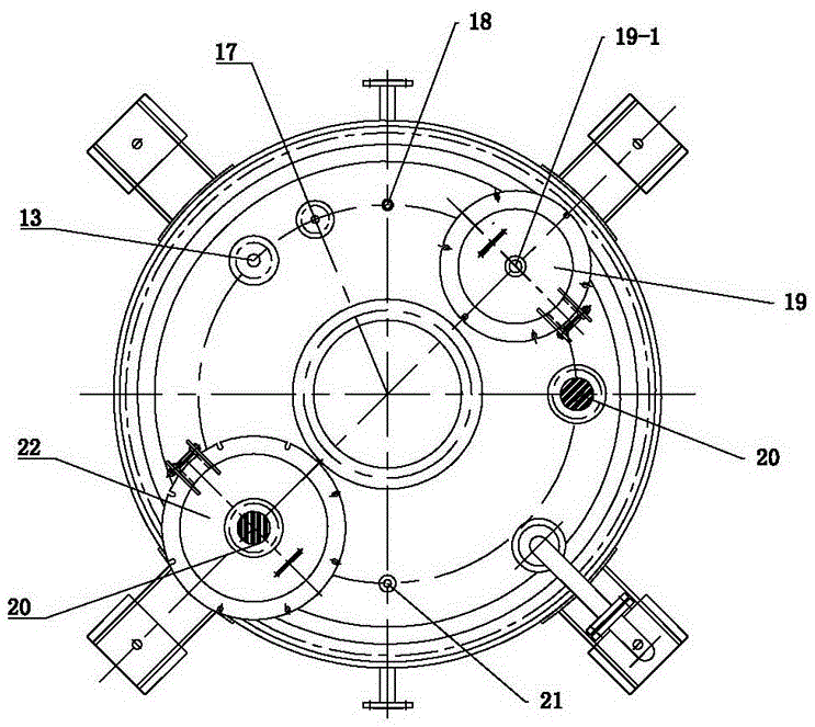
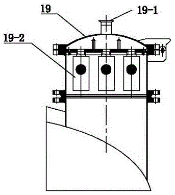
[0016] Such as figure 1 , figure 2 As shown, the ribbon vacuum dryer of the present invention includes: a mixing dryer A, which includes: a cylinder body 1, a cylinder cover 2, a bracket 3, a motor 4, a reduction box 5, a stirring shaft 6, a bearing 7, a mechanical seal 8, Support rod 9, double spiral belt 10, baffle plate 11, hot water inlet 12, hot water outlet 13, sewage outlet 14, nitrogen inlet 15, material outlet 16, spare port 17, thermometer port 18, manhole 19, pump Vacuum port 19-1, sight glass 20, vacuum port 21, feeding port 22, water pipe 23, jacket 24, insulation layer 25, scraper 26.

[0017] The upper part of the conical cylinder 1 is provided with a detachable cylinder cover 2, the upper part of the cylinder cover 2 is connected with a hollow bracket 3, the motor 4 and the reduction box 5 are installed on the top of the bracket 3, and the stirring shaft 6 is vertically installed on the bracket 3 through the bearing 7 The inside and the upper end are connect...


PUM


Abstract

The invention relates to a helical ribbon vacuum dryer and a working method thereof. The helical ribbon vacuum dryer comprises a barrel body, wherein the upper part of the barrel body is provided with a barrel cover, a hollow support is arranged at the upper part of the barrel cover, the upper part of a stirring shaft is in vertical and rotary fit to the inside of the support, and the middle-lower part of the stirring shaft is located in the barrel body; double helical ribbons are distributed in the middle lower part of the stirring shaft, the outer edges of the double helical ribbons are distributed close to the inner wall of the barrel body; a concave scraper matched with the inner wall of the bottom of the barrel body is arranged at the lower end of the stirring shaft; and the top of the concave scraper does not exceed the bottom of the double helical ribbons. According to the invention, the top of the concave scraper does not exceed the bottom of the double helical ribbons, namely the scraper and the double helical ribbons are distributed up and down, and force application area of the scraper and the double helical ribbons acting on the material is relatively small, thus preventing overall movement in movement of the material in a whole container and avoiding material caking.

Description

technical field [0001] The invention relates to a ribbon vacuum dryer, which is used for drying, crushing, vacuum decompression and mixing of materials, and can cool the circulating gas and remove impurities. It is a multifunctional fully enclosed mixing drying equipment. Background technique [0002] In the production process of pharmaceutical, chemical, pesticide, food and other industries, the powder needs to be dried, and at the same time, a variety of powders or materials must be fully mixed, and a mixing and drying equipment is needed. Most raw materials in pharmaceutical production are heat-sensitive, so material agglomeration often occurs during the drying process, which requires shortening the drying time as much as possible and improving drying efficiency. The purity of the circulating gas used in the drying process will greatly affect the quality of the drug. big impact. Existing mixing dryers can meet the above, but there are deficiencies. As the application pu...

Claims


Application Information

Patent Timeline
Patent Type & Authority Applications(China)
IPC IPC(8): F26B11/16F26B25/04F26B23/10F26B25/00F26B7/00
CPCF26B11/14F26B7/00F26B23/10F26B25/00F26B25/04
Inventor 陆文光
Owner 陆文光
Why Eureka
Try Eureka