


Quick Research
Generate reliable direction feasibility study reports for your R&D in just a few steps.

Technical Q&A
Discover and master advanced knowledge NOW. Basics, ideas, possibilities, all at once.

Find Solutions
As an expert in R&D theories, this can generate solutions to your technical problems instantly.

Evaluate Feasibility
Analyze your overall solution with one click, know your potential R&D risks in advance.

Monitor Landscape
Get weekly tech updates, stay abreast of the latest tech innovations and key insights.
Air valve structure
A gas valve and valve body technology, applied in the field of compressed gas decompression devices, can solve the problems of low pressure regulation accuracy, poor use stability, small pressure regulation range, etc., and achieve the advantages of small influencing factors, simple structure and many control points Effect
- Summary
- Abstract
- Description
- Claims
- Application Information
AI Technical Summary
Problems solved by technology
Method used
Image

Examples
Embodiment 1
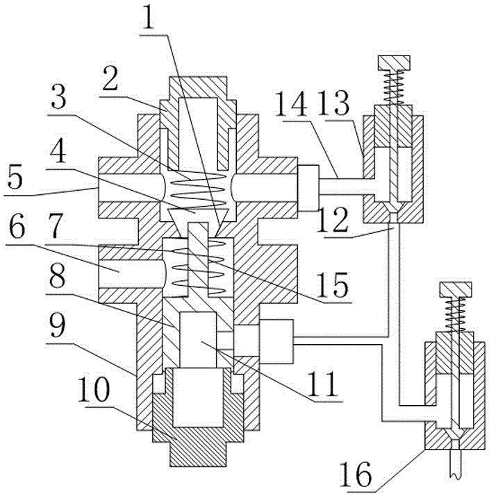
[0021] Such as figure 1 As shown, a gas valve structure includes a valve body 9, an inlet passage 5 and an outlet passage 6 are arranged on the valve body 9, and a decompression portion communicating with the inlet passage 5 and the outlet passage 6 is arranged in the valve body 9. The decompression part includes a valve core 4 and a valve seat 1 arranged on the valve body 9. The valve body 9 is also screwed with a pressure seat 2, and a first spring 3 is arranged between the pressure seat 2 and the valve core 4. It also includes a regulating valve. The valve and the piston chamber 11 arranged in the valve body 9, the piston chamber 11 is arranged on the side of the decompression part close to the outlet passage 6, the piston chamber 11 is also provided with a piston 8, and the piston 8 is near the side of the valve core 4 One side is provided with a connecting rod 15 for fixedly connecting the piston 8 and the valve core 4, the intake end of the regulating valve communicates ...
Embodiment 2
[0026] The present embodiment is further limited on the basis of embodiment 1, as figure 1 As shown, in order to reduce the change speed of the channel area for gas flow between the valve core 4 and the valve seat 1 during the movement of the valve core 4, that is, to improve the controllability of the flow channel area, the valve seat 1 and the valve core The cross-sections of 4 are conical, and the valve seat 1 and the larger end of the valve core 4 are close to the inlet channel 5 . The above structure also facilitates the sealing of the valve core 4 and the valve seat 1 in the cut-off state of the present invention.
[0027] In order to facilitate the processing, assembly and maintenance of the present invention, the valve body 9 is provided with a straight through hole, the valve seat 1 is a diameter-reducing structure on the straight through hole, and one end of the straight through hole is threadedly connected to the pressure seat 2, directly The other end of the throu...
Embodiment 3
[0030] This embodiment is further limited on the basis of the above embodiments, as figure 1 As shown, in order to optimize the flow adjustment performance of the pressure regulating valve 13 and the relief valve 16, both the regulating valve and the relief valve 16 are cut-off valves.
[0031] In order to further optimize the above-mentioned flow adjustment performance, the sealing surface of the cut-off valve is tapered.
PUM
 Abstract
Description
Claims
Application Information
 - R&D Engineer
- R&D Manager
- IP Professional
- Industry Leading Data Capabilities
- Powerful AI technology
- Patent DNA Extraction
Browse by: Latest US Patents, China's latest patents, Technical Efficacy Thesaurus, Application Domain, Technology Topic, Popular Technical Reports.
© 2024 PatSnap. All rights reserved.Legal|Privacy policy|Modern Slavery Act Transparency Statement|Sitemap|About US| Contact US: help@patsnap.com