Automatic dredging torrent tank

A rapid trough, automatic technology, applied in the field of rapid trough, can solve the problem that the silt is not easy to remove, and achieve the effect of convenient operation

Inactive Publication Date: 2016-06-29
韦积分
View PDF7 Cites 5 Cited by
  • Summary
  • Abstract
  • Description
  • Claims
  • Application Information

AI Technical Summary

Problems solved by technology

[0003] The technical problem to be solved by the present invention is to provide an automatic dredging rapids tank, which can solve the problem that the sludge deposited at the bottom of the existing rapids tank is not easy to remove

Method used


Image

  • Automatic dredging torrent tank
  • Automatic dredging torrent tank
  • Automatic dredging torrent tank

Examples


Embodiment 1

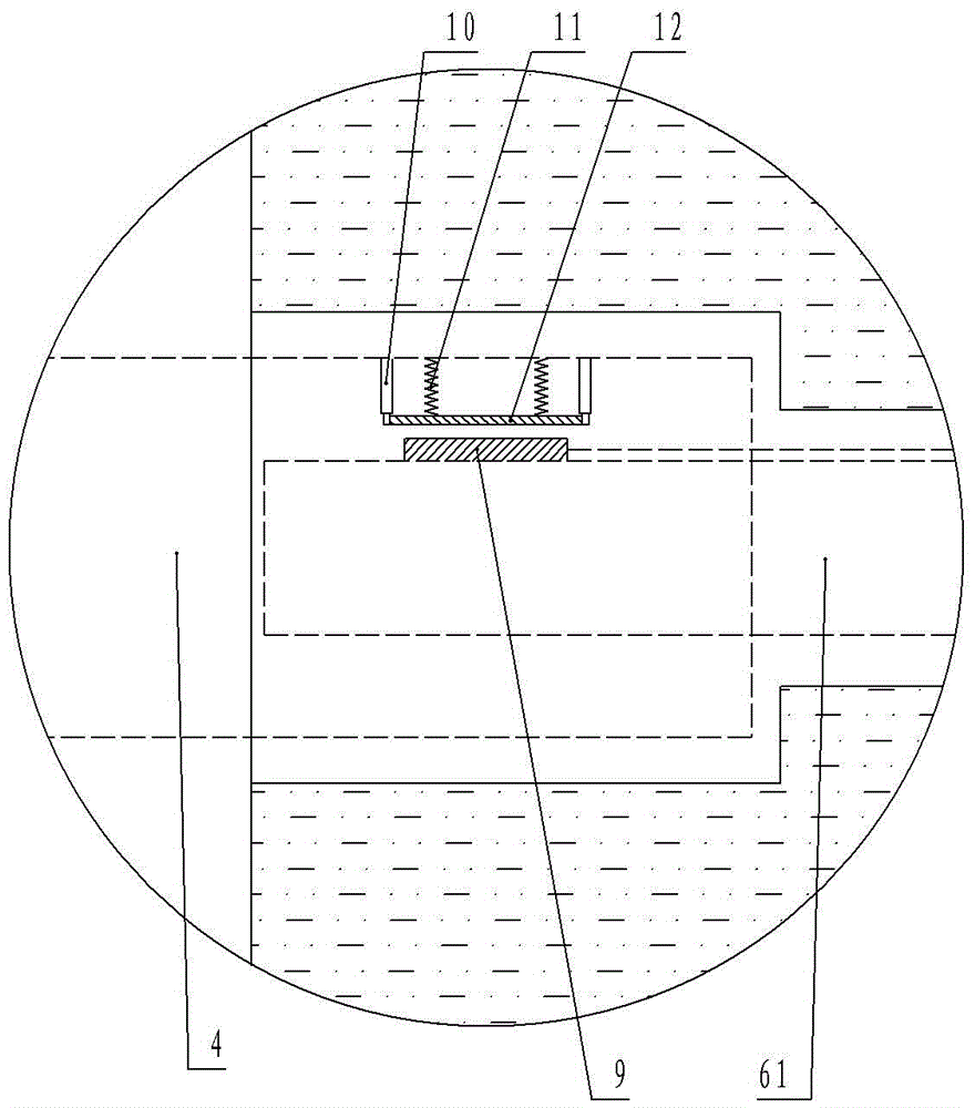
[0016] figure 1 , figure 2 The shown automatic dredging rapid flow tank includes a tank body 1. A shallow pool is opened at the bottom of the tank body 1 along the direction of water flow. Two reels are movably installed between the two side walls at both ends of the shallow pool. The reels include The first reel 2 and the second reel 4, the two ends of the first reel 2 and the second reel 4 are respectively sleeved with rotating wheels, the rotating wheels are respectively sleeved with an annular dredging belt 3, the upper edge of the annular dredging belt 3 The belt is flush with the bottom of the tank 1; a control room b is opened on one side of the tank 1, and a motor 6 is arranged in the control room b, such as image 3 As shown, the output shaft 61 of the motor 6 passes through the wall between the tank 1 and the control room b and is inserted into the corresponding end of the first reel 2. The inner wall of the reel at this end is provided with a radially extending teles...

Embodiment 2

[0019] The output shaft 61 of the motor 6 passes through the wall between the tank 1 and the control room b and is installed in the corresponding end of the second reel 4, and the rest is the same as the first embodiment.


PUM


Abstract

The invention discloses an automatic dredging torrent tank and belongs to the technical field of municipal road engineering facilities. The torrent tank comprises a tank body, the bottom of the tank body is provided with a shallow pool in the water flow direction, two winding drums are movably mounted between the two side walls of the two ends of the shallow pool, each winding drum is provided with a rotating wheel sleeved with an annular dredging belt, and the upper edge belts of the annular dredging belts are flush with the bottom of the tank body; one side of the tank body is provided with a control chamber, the control chamber is internally provided with a motor, an output shaft of the motor penetrates through a wall between the tank body and the control chamber and is mounted at the corresponding end of one of the winding drums in a penetrating mode, the inner wall of the winding drum at the end is provided with a stretching and contracting pillar which stretches out in the radial direction, the stretching end of the stretching and contracting pillar is connected with an iron plate, springs are connected between the iron plate and the inner wall of the corresponding winding drum, an electromagnet is arranged at the position, corresponding to the iron plate, on the output shaft, and both the electromagnet and the motor are connected with a control switch through a controller. By means of the automatic dredging torrent tank, the problem that sludge deposited at the bottom of an existing torrent tank is not removed easily can be solved.

Description

Technical field [0001] The invention relates to the technical field of municipal road engineering facilities, in particular to a rapid chute for road engineering. Background technique [0002] Rapid flow trough refers to a trench that is set on steep slopes or deep ditch sections with a relatively steep slope and the water does not leave the bottom of the trough. It is usually set on the high embankment side slope, the high cutting side slope, the junction of the road cutting and the high embankment, the upper and lower gutters of the turning curve, etc., to drain water and achieve the purpose of slowing down the flow of water, and play a great role in protecting the roadbed. However, the existing rapid chute generally has an open structure, which is easy to accumulate rubbish and foreign matter, deposit mud, and block the rapid chute, causing rainwater to overflow and scour the roadbed. In order to reduce the entry of foreign matter into the rapid chute, people set up a rapid c...

Claims


Application Information

Patent Timeline
Patent Type & Authority Applications(China)
IPC IPC(8): E01C11/22
CPCE01C11/227
Inventor 韦积分
Owner 韦积分
Why Eureka
Try Eureka