


Quick Research
Generate reliable direction feasibility study reports for your R&D in just a few steps.

Technical Q&A
Discover and master advanced knowledge NOW. Basics, ideas, possibilities, all at once.

Find Solutions
As an expert in R&D theories, this can generate solutions to your technical problems instantly.

Evaluate Feasibility
Analyze your overall solution with one click, know your potential R&D risks in advance.

Monitor Landscape
Get weekly tech updates, stay abreast of the latest tech innovations and key insights.
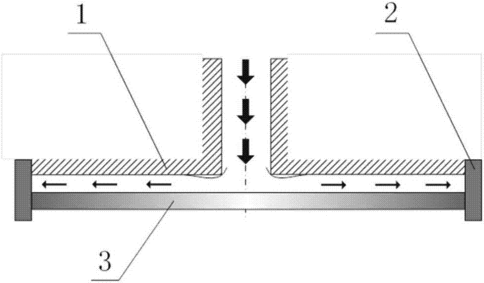
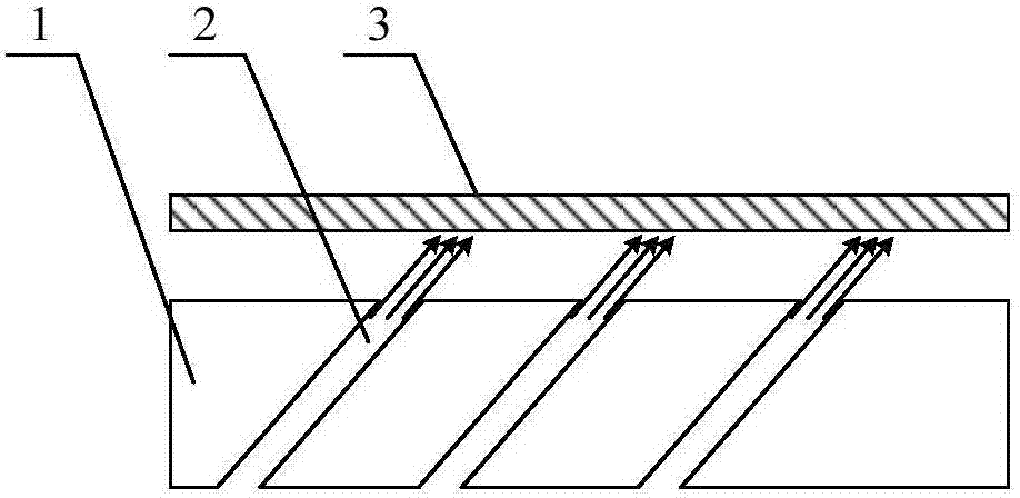
A control method for a contactless transport and positioning platform device
A technology of positioning platform and control method, which is applied to conveyor control devices, transportation and packaging, conveyors, etc., can solve the problems of lack of object pose detection and control functions, unfavorable for workpiece motion control, and small workpiece motion acceleration. Achieve the effect of suppressing unstable vibration phenomenon, excellent control performance, and easy realization
- Summary
- Abstract
- Description
- Claims
- Application Information
AI Technical Summary
Problems solved by technology
Method used
Image


Examples
Embodiment Construction
[0050] Such as Figure 4 to Figure 10 As shown, in the non-contact transportation and positioning platform device of the present invention, the transportation platform 2 is supported above the fixed platform 4 by the leveling nut 3, and the leveling nut 3 can adjust the levelness of the transportation platform 2; the fixed platform 4 and the base Seat 8 is rigidly connected by threaded fixed platform support 15, forming a space for installing pneumatic solenoid valve group 7 and pipelines, pneumatic solenoid valve group 7, flow meters 6a, 6b, valve seat manifolds 9a, 9b, pressure reducing valve 5a, 5b are mounted on the base 8 .
[0051] The positive pressure gas source is connected to the positive pressure reducing valve 5a through the connecting hose 15a, the output end of the positive pressure reducing valve 5a is connected through the intake hose 14a of the flowmeter, and the output end of the flowmeter 6a is converging through the valve seat The intake hose 13a of the pl...
PUM
 Abstract
Description
Claims
Application Information
 - R&D Engineer
- R&D Manager
- IP Professional
- Industry Leading Data Capabilities
- Powerful AI technology
- Patent DNA Extraction
Browse by: Latest US Patents, China's latest patents, Technical Efficacy Thesaurus, Application Domain, Technology Topic, Popular Technical Reports.
© 2024 PatSnap. All rights reserved.Legal|Privacy policy|Modern Slavery Act Transparency Statement|Sitemap|About US| Contact US: help@patsnap.com