


Quick Research
Generate reliable direction feasibility study reports for your R&D in just a few steps.

Technical Q&A
Discover and master advanced knowledge NOW. Basics, ideas, possibilities, all at once.

Find Solutions
As an expert in R&D theories, this can generate solutions to your technical problems instantly.

Evaluate Feasibility
Analyze your overall solution with one click, know your potential R&D risks in advance.

Monitor Landscape
Get weekly tech updates, stay abreast of the latest tech innovations and key insights.
Propeller hub cap with fins
A propeller hub and propeller technology, applied to rotating propellers, rotary propellers, ship propulsion, etc., can solve the problems of reducing pressure difference, hindering propulsion efficiency, and not greatly reducing hub vortex cavitation, so as to improve propulsion efficiency effect
- Summary
- Abstract
- Description
- Claims
- Application Information
AI Technical Summary
Problems solved by technology
Method used
Image

Examples
Embodiment Construction
[0044] Hereinafter, embodiments of the present invention will be described in detail with reference to the accompanying drawings.
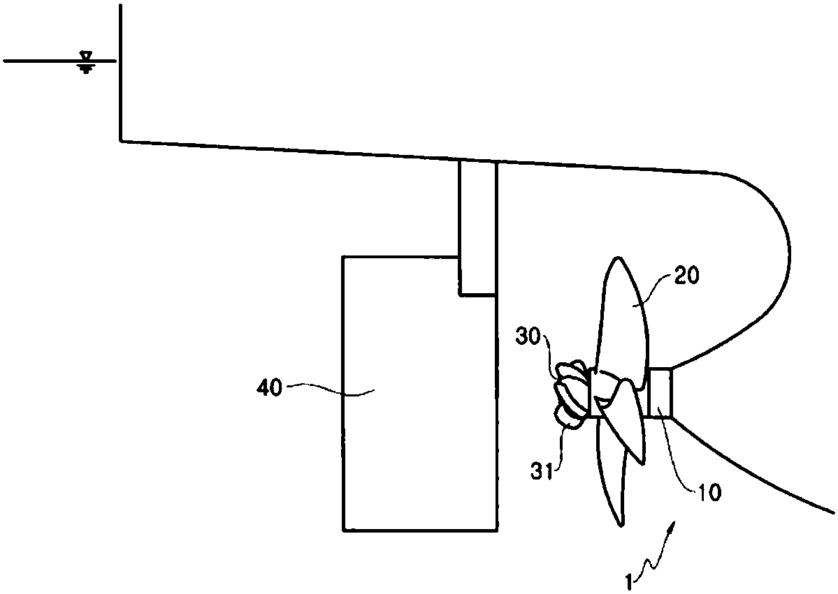
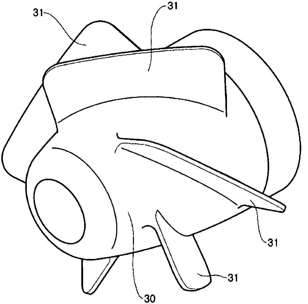
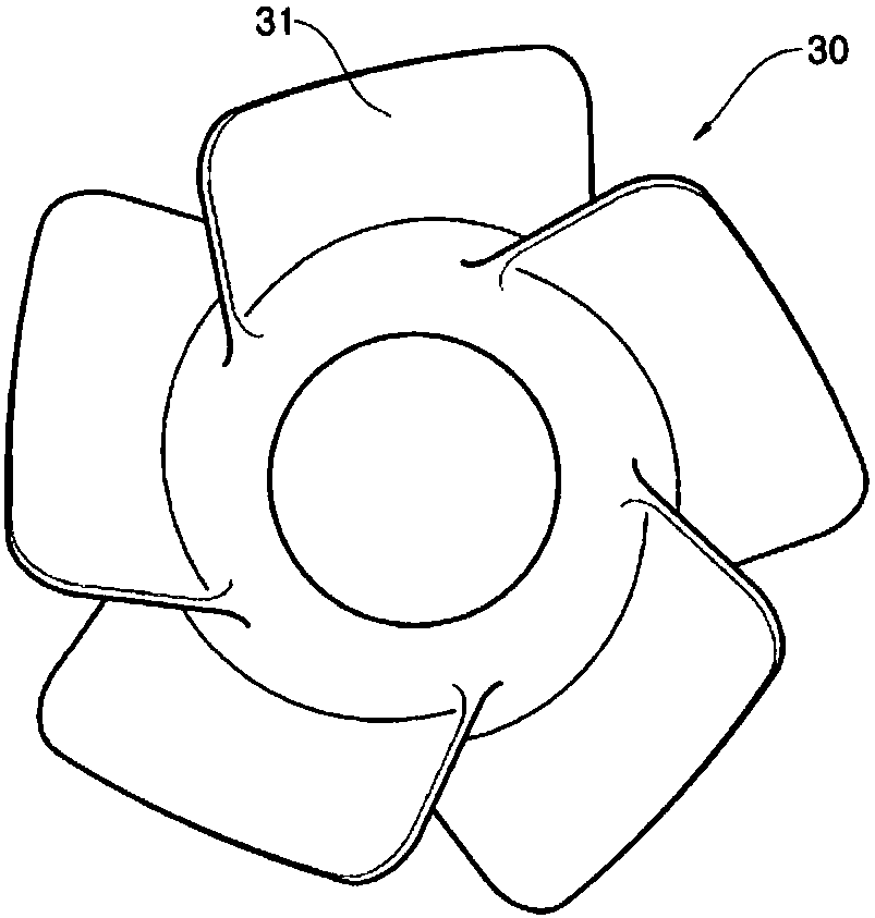
[0045] Figure 5 is a perspective view showing a hub cap according to the present invention. Such as Figure 5 As shown, a hub cap 100 according to the present invention includes a plurality of fins 110 formed along a perimeter, and an end plate 111 formed at the end of each fin 110 .
[0046] Figure 6 for showing Figure 5 A side view of the hub cap 100 of , and depicts the arrangement of the fins 110 formed along the periphery of the hub cap 100 . The fins 110 are disposed along the circumference of the hub cap 100 in a helical form.
[0047] Figure 7 A side view of the fin 110 of the hub cap 100 according to the present invention is shown. The end plate 111 is formed on the end of the fin 110, and the end plate 111 plays a role of preventing fluid flow, which is between the front (propeller side) surface and the rear (rudder side) surf...
PUM
 Abstract
Description
Claims
Application Information
 - R&D Engineer
- R&D Manager
- IP Professional
- Industry Leading Data Capabilities
- Powerful AI technology
- Patent DNA Extraction
Browse by: Latest US Patents, China's latest patents, Technical Efficacy Thesaurus, Application Domain, Technology Topic, Popular Technical Reports.
© 2024 PatSnap. All rights reserved.Legal|Privacy policy|Modern Slavery Act Transparency Statement|Sitemap|About US| Contact US: help@patsnap.com