
PBA driving circuit based on PWM dimming

A technology of driving circuit and dimming power supply, which is applied in the direction of lamp circuit layout, light source, electric light source, etc.

Inactive Publication Date: 2016-06-22
SHANGHAI AVIATION ELECTRIC
View PDF4 Cites 3 Cited by
  • Summary
  • Abstract
  • Description
  • Claims
  • Application Information

AI Technical Summary

Problems solved by technology

However, there is a parasitic capacitance between the poles of the field effect tube, which should be paid attention to when designing the circuit.

Method used


Image

  • PBA driving circuit based on PWM dimming

Examples


Embodiment Construction

[0011] The present invention will be described in detail below in conjunction with the accompanying drawings and embodiments.

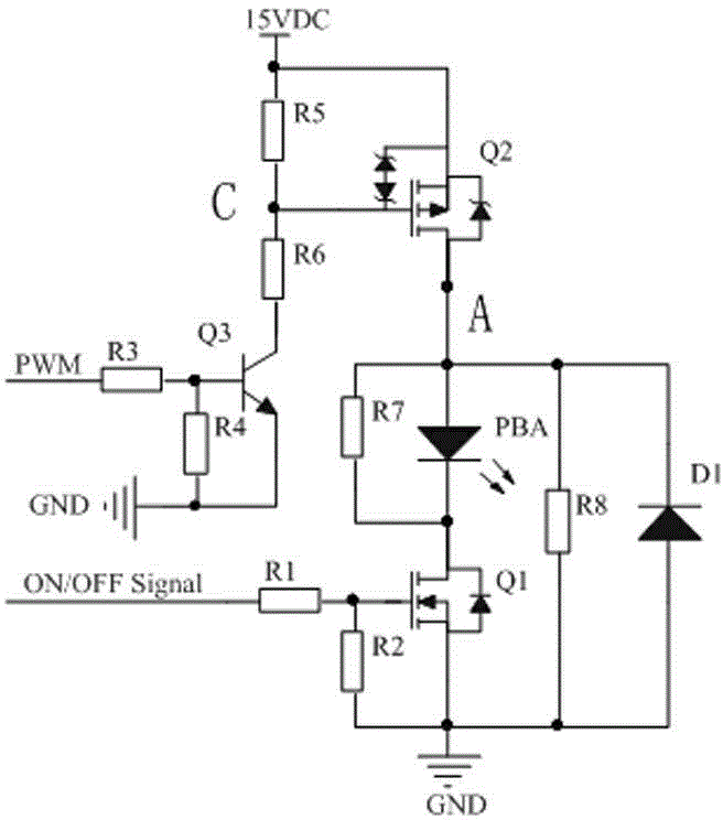
[0012] as attached figure 1 As shown, a PBA drive circuit based on PWM dimming consists of three circuits, namely: PWM dimming power supply circuit, PBA switch circuit, waveform adjustment and PBA anti-dimmer circuit.

[0013] PWM dimming power supply circuit, after the PWM signal is divided by the third resistor R3 and the fourth resistor R4, the high-level voltage is clamped to 0.7V (the conduction voltage drop of the transistor), so that the transistor Q3 is in the switching state. When the triode Q3 is turned on, the voltage at point C is 7.5V (ignoring the turn-on voltage drop of Q3ce), so that the second field effect transistor (P-channel MOS transistor) Q2 is turned on, and the moment when it starts to turn on, the gap between the gate and the drain The parasitic capacitance C gd Discharge to the ground through the sixth resistor R6 and the t...


PUM


Abstract

The invention provides a PBA driving circuit based on PWM dimming. The PBA driving circuit based on PWM dimming comprises a PBA dimming light source circuit and a PBA switch circuit. The PBA driving circuit based on PWM dimming is characterized in that the PBA dimming power source circuit is connected with a PWM signal input end, a dimming light source is outputted according to a PWM signal, the PBA switch circuit comprises a first field effect transistor, an input end of the field effect transistor is connected with a switch signal input end, a source electrode of the first field effect transistor is in ground connection, a drain electrode of the first field effect transistor is connected with a negative electrode of the PBA, and a positive electrode of the PBA is connected with an output end of the PBA dimming light source circuit. According to the PBA driving circuit, a problem that the PBA is driven by both a dimming signal and a switch signal is solved, the dimming method is realized through adjusting a PWM duty ratio, closing and opening of the PBA are realized through controlling conduction of an MOS tube, and a problem of micro brightness of an LED in the PBA during closing is solved.

Description

technical field [0001] The invention relates to a PBA drive circuit design, in particular to the PBA drive circuit based on PWM dimming in airborne equipment. Background technique [0002] Illuminated Push Button Switches and Annunciators PBA (Illuminated Push Button Switches and Annunciators) is an indispensable electrical component in airborne equipment. It is mainly used for information indication and control input. High requirements, and the circuit design will be constrained by factors such as cost, so it will be difficult to meet the above conditions at the same time. If the PBA can be driven by a transistor or a field effect transistor, the field effect transistor is a voltage control element. Transistors are current-steering elements. In the case that only a small current is allowed to be obtained from the signal source, a field effect transistor should be selected; and in a condition where the signal voltage is low and a large current is allowed to be obtained from...

Claims


Application Information

Patent Timeline
IPC IPC(8): H05B37/02
Inventor 崔利家
Owner SHANGHAI AVIATION ELECTRIC
Learn More