Heating board structure

A heating plate and fixing plate technology, which is applied in the manufacture of motor generators, electrical components, electromechanical devices, etc., can solve the problems of complex structure of the heating device and unsatisfactory heating and drying effect, and achieve the effect of simple structure and convenient installation.

Inactive Publication Date: 2016-06-22
WUXI FORMEN TECHN
View PDF0 Cites 0 Cited by
  • Summary
  • Abstract
  • Description
  • Claims
  • Application Information

AI Technical Summary

Problems solved by technology

[0002] Motor rotors are mostly the main rotating parts in power machinery and working machinery. They need to be cleaned during the rotor processing engineering. After cleaning on the assembly line, they need to be painted. Generally, they need to be left for a period of time after painting. Drying for subsequent operation, because it is an assembly line operation, the cleaning and painting of motor rotors is fast, and a space for a large number of motor rotors is required, so a heating device is placed behind the painting to facilitate the rapid drying of the paint, but common The structure of the heating device is complicated, and the heating and drying effect is not ideal

Method used


Image

  • Heating board structure
  • Heating board structure

Examples


Embodiment Construction

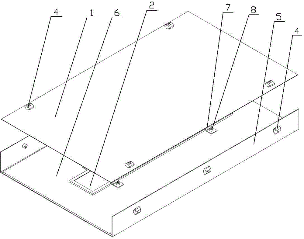
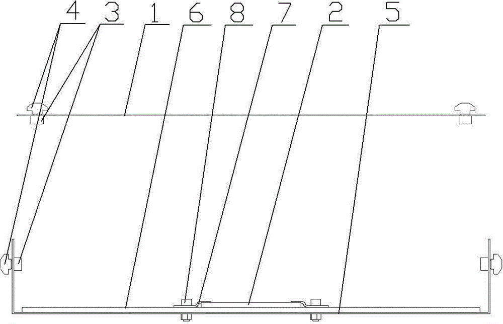
[0010] See figure 1 , figure 2 As shown, a heating plate structure includes a heating upper plate 1 and a heating lower plate 2, the upper end of the heating upper plate 1 is installed with a fixing block 4 through bolts 3, the heating lower plate 2 is installed on a U-shaped fixing plate 5, and the U-shaped fixing plate 5. Fixing blocks 4 are respectively installed on the outside of both sides through bolts 3. The fixing block 4 is in the shape of a plane with a plane on the upper end. There is a gap between the two sides of the fixing block 4 and the heating upper plate 1 and the U-shaped fixing plate 5, which is convenient. It is embedded in the T-shaped card slot of the profile or in the T-shaped guide rail; the upper end of the heating upper plate 1 is evenly installed with four fixing blocks 4 through bolts 3, and the outer sides of the U-shaped fixing plate 5 are respectively installed with three bolts 3 in a straight line The fixed block 4 arranged can realize better...


PUM


Abstract

The invention relates to the heating equipment technology field and particularly relates to a heating board structure which has a simple structure and can excellently realize drying operation on paint on a motor rotor. The heating board structure comprises an upper heating board and a lower heating board, wherein an upper end of the upper heating board is equipped with a fixing block through a bolt, the lower heating board is mounted on a U-shaped fixing board, outer portions of two sides of the U-shaped fixing board are respectively equipped with the fixing block through bolts, the upper end of the fixing block is a planar umbrella-shaped structure, and two sides of the fixing block, the upper heating board and the U-shaped fixing board have gaps.

Description

technical field [0001] The invention relates to the technical field of heating equipment, in particular to a heating plate structure. Background technique [0002] Motor rotors are mostly the main rotating parts in power machinery and working machinery. They need to be cleaned during the rotor processing engineering. After cleaning on the assembly line, they need to be painted. Generally, they need to be left for a period of time after painting. Drying for subsequent operation, because it is an assembly line operation, the cleaning and painting of motor rotors is fast, and a space for a large number of motor rotors is required, so a heating device is placed behind the painting to facilitate the rapid drying of the paint, but common The structure of the heating device is complicated, and the effect of heating and drying is not ideal. Contents of the invention [0003] In order to solve the above problems, the present invention provides a heating plate structure, which has ...

Claims


Application Information

Patent Timeline
Patent Type & Authority Applications(China)
IPC IPC(8): H02K15/12
Inventor 田芸
Owner WUXI FORMEN TECHN
Why Eureka
Try Eureka