
Electric machine

A machine and shaft technology, applied in the field of motors, can solve the problems of high production costs, achieve the effects of increasing power, reducing axial extension size, and avoiding overheating

Active Publication Date: 2016-06-22
BAUMULLER NURNBERG GMBH
View PDF9 Cites 0 Cited by
  • Summary
  • Abstract
  • Description
  • Claims
  • Application Information

AI Technical Summary

Problems solved by technology

Therefore, the production cost is relatively high

Method used


Image

  • Electric machine
  • Electric machine
  • Electric machine

Examples


Embodiment Construction

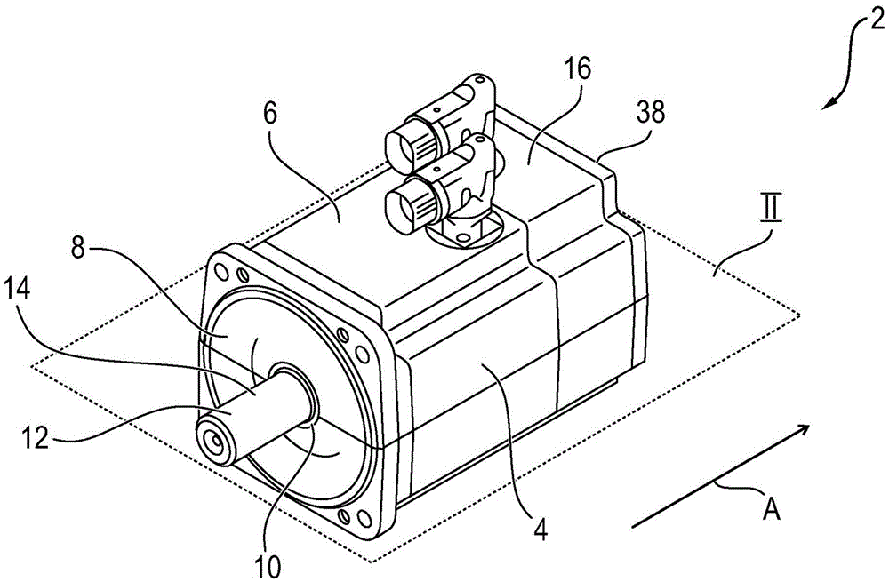
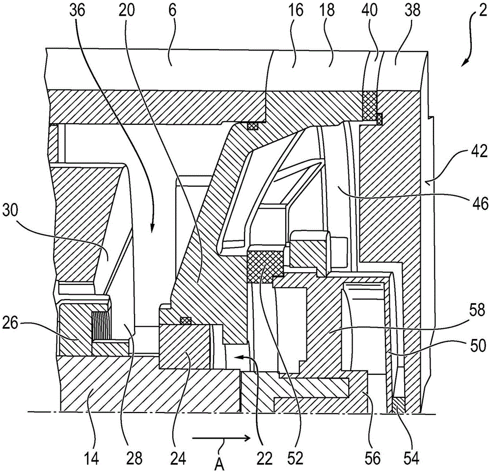
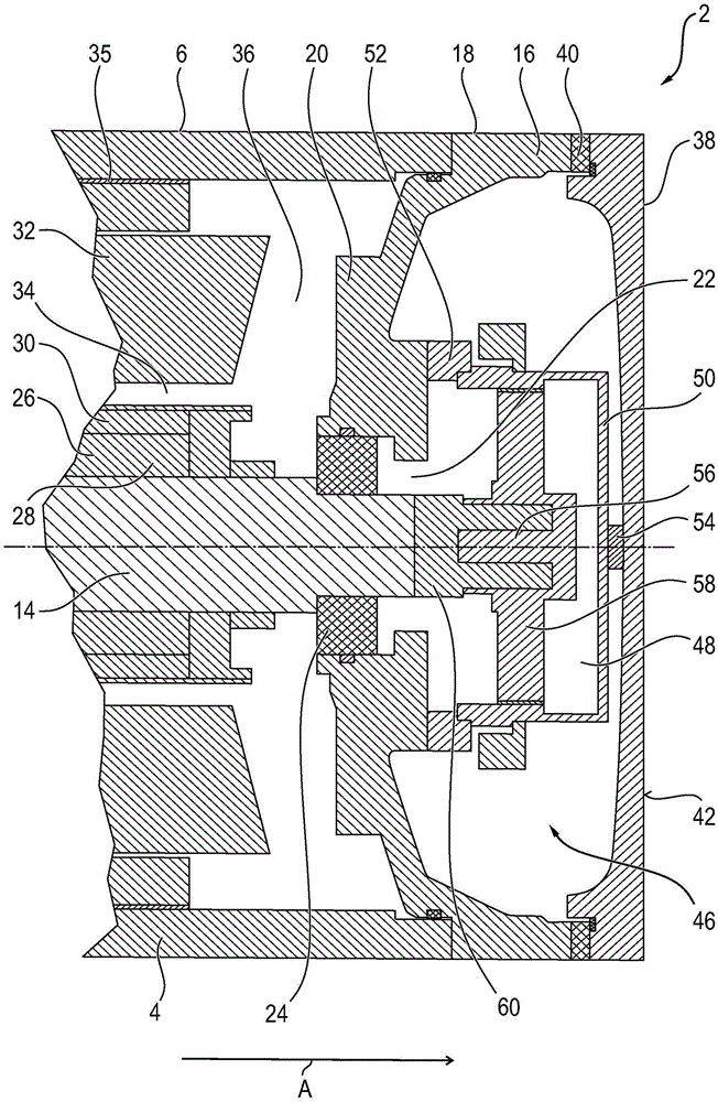
[0028] exist figure 1 The diagram shows an electric machine 2 in the form of an alternating current synchronous motor with a maximum power of 5 kW in a perspective view. The electric machine 2 includes a machine housing 4 made of aluminum. The machine housing 4 itself has a hollow-cylindrical central section 6 , on one end side of which an A-side bearing cap 8 with a ball bearing 10 is fastened. The journal 12 of the crankshaft 14 , which is made of steel, passes through the central recess formed by means of the ball bearing 10 . In the installed state, the structural elements operated by the electric motor 2 are connected to the journal 12 . In other words, the journal 12 forms the drive side of the electric motor 2 . On the side of the middle section 8 opposite the A-side bearing cap 8 , the B-side bearing cap 16 is connected to the middle section 6 , wherein the B-side bearing cap 16 has a collar 18 which is connected to the center Section 6 is aligned. The central sec...


PUM


Abstract

The invention relates to an electric machine (2), especially a motor for industrial equipment. The electric machine comprises a spindle (14) which is supported rotatably by a bearing (24) of a bearing cover (16) on the B side of a machine housing (4) and is connected with a sensor shaft (56) of a rotation sensor (48). The sensor shaft (56) and the machine shaft (14) are arranged concentrically and is supported rotatably by a rotation sensor stator (50) of the rotation sensor (48). The rotation sensor (48) is positioned between the B-side bearing cover (16) and a machine shield (38) connected to the machine housing (4). A first heat isolation component (40) is arranged between the machine housing (4) and the machine shield (38).

Description

technical field [0001] The invention relates to an electric machine with a crankshaft which is rotatably mounted via a bearing of a B-side bearing cover of a machine housing and which is coupled to a sensor shaft of a rotation sensor. Electric motors are especially integral parts of industrial equipment. Background technique [0002] Industrial equipment has many actuators, each of which is operated by an electric motor. The actuator is mostly designed as an inner rotor and therefore includes a rotor arranged inside the stator. For precise control of the actuators driven by the individual electric motors it is necessary to know the exact angular position of the rotor relative to the stator. Usually a rotation sensor coupled to the motor shaft is used for this purpose. Rotary sensors usually have two capacitive sensor elements that are offset relative to the axis of rotation of the motor shaft. The component part of the rotary sensor coupled to the motor shaft consists of...

Claims


Application Information

Patent Timeline
Patent Type & Authority Applications(China)
IPC IPC(8): H02K11/21
CPCH02K5/15H02K11/225
Inventor 罗伯特·席克乔鲍·迪克汉斯-于尔根·布劳奈泽赫尔穆特·塞普斯特凡·博伊尔莱因弗兰克·古特雅尔
Owner BAUMULLER NURNBERG GMBH
Learn More