A photovoltaic grid-connected power generation system based on medium and high voltage direct current access

A technology for DC power generation and grid-connected power generation, applied in the field of solar photovoltaic power generation, can solve the problems of weak immunity, long capital operation cycle, high initial investment cost of new energy power generation, and achieve the effect of reducing line loss

Active Publication Date: 2019-06-25
TBEA SUNOASIS +1
View PDF5 Cites 0 Cited by
  • Summary
  • Abstract
  • Description
  • Claims
  • Application Information

AI Technical Summary

Problems solved by technology

[0005] (1) In each centralized photovoltaic grid-connected power generation unit 100, a low-voltage transmission line (the voltage on the line is less than 1kV) for wiring, and the low-voltage and high-current parallel connection method is used, which leads to the problems of long low-voltage and high-current transmission lines and excessive line loss (line loss is usually 2%-3% of the total system), and this problem Will further deteriorate with the increase of power generation scale and capacity
[0006] (2) At present, due to the limitation of DC loss and the capacity of low-voltage photovoltaic grid-connected inverters, large-scale photovoltaic power plants usually need to configure dozens or even hundreds of low-voltage photovoltaic grid-connected inverters and corresponding inverter rooms and power distribution, Monitoring equipment
The maximum power of low-voltage photovoltaic grid-connected inverter products in the industry is generally 500kW. If a centralized photovoltaic grid-connected power generation unit 100 includes a 1MW photovoltaic array, for a 20MW photovoltaic power station, 20 inverters need to be configured. Each inverter room needs to be equipped with two sets of combiner boxes 1012, two sets of DC power distribution cabinets 1013, two sets of low-voltage photovoltaic grid-connected inverters 1014, and one set of power frequency step-up transformers 102. The initial investment cost is high, the capital operation cycle is long, and the overall return on investment is low
[0007] (3) It has been verified by experiments that the maximum power tracking of the output power of the photovoltaic array is carried out through the low-voltage photovoltaic grid-connected inverter, and its MPPT penetration rate is low. shadows of objects and the inconsistency of the characteristics of each photovoltaic array) the immunity to interference is also relatively weak
[0008] (4) The peak efficiency of the current mainstream low-voltage photovoltaic grid-connected inverter products is nominally 98.7%, and its actual efficiency in the actual operation process is about 97%. If the focus and energy of research, analysis and optimization continue to be concentrated on For a single photovoltaic grid-connected power electronic device (that is, a single centralized photovoltaic grid-connected power generation unit), there is not much room for improvement, no matter from the perspective of efficiency or cost. Only by solving the problem can the whole system be further and deeply optimized

Method used


Image

  • A photovoltaic grid-connected power generation system based on medium and high voltage direct current access
  • A photovoltaic grid-connected power generation system based on medium and high voltage direct current access

Examples


Embodiment

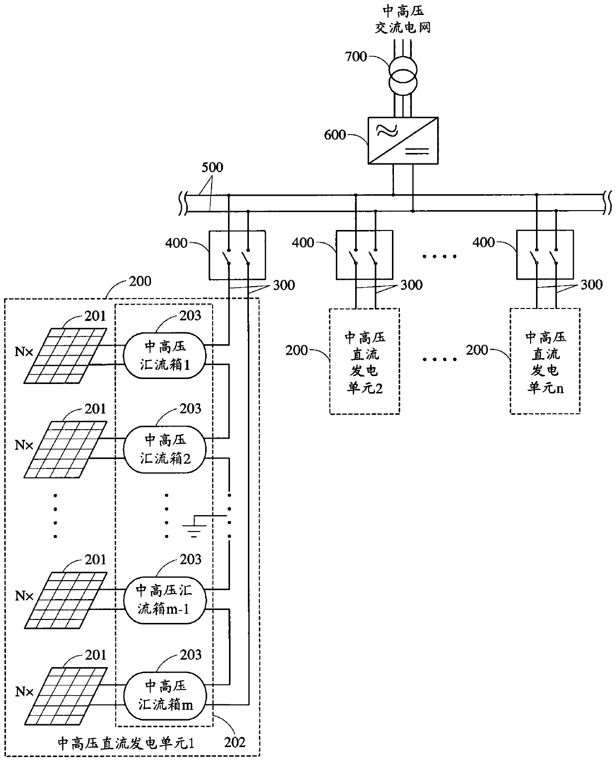
[0039] Such as figure 2 As shown, this embodiment provides a photovoltaic grid-connected power generation system based on medium and high voltage DC access, which includes: n medium and high voltage DC power generation units 200, n isolation switches 400 and 1 medium and high voltage centralized photovoltaic grid-connected inverter Inverter 600, wherein, n is an integer greater than 0, and the number of medium and high voltage DC power generation units 200 is the same as that of isolating switches 400 and corresponds to each other. Each medium and high voltage DC power generation unit 200 is connected in parallel through its corresponding isolating switch 400. By increasing the number of medium and high voltage DC power generation units 200 and their corresponding isolating switches 400, the capacity of the system can be easily increased and expanded; moreover, each medium The high-voltage DC power generation unit 200, each isolating switch 400 and the medium and high-voltage...


PUM


Abstract

The invention provides a photovoltaic grid-connected power generation system based on middle and high voltage direct current access. The system comprises at least one middle and high voltage direct current power generation unit and a middle and high voltage centralized PV grid-connected inverter. Each of the direct current power generation unit comprises multiple groups of PV arrays and cascaded direct current boost units. Each group of the PV arrays comprises a plurality of arrays which are connected in parallel. The output end of each group of PV arrays is connected to the input end of one cascaded direct current boost unit. The output end of the cascaded direct current boost unit is connected to one path of middle voltage and high voltage direct current bus and is used for raising the direct current voltage outputted by each group of PV arrays and carrying out bus out in a mode of series connection to the path of middle voltage and high voltage direct current bus. Each path of middle voltage and high voltage direct current bus which is respectively connected to the output end of each of the cascaded direct current boost units is connected in parallel to form a path of middle voltage and high voltage direct current bus which then is connected to the direct current side of the middle and high voltage centralized PV grid-connected inverter, and the alternating current side is connected to a middle and high voltage alternating current power grid. According to the photovoltaic grid-connected power generation system, the line loss can be reduced, and the cost can be reduced.

Description

technical field [0001] The invention is applied in the technical field of solar photovoltaic power generation, and relates to the design of a photovoltaic system collector circuit and grid-connected connection technology based on medium-high voltage direct current access, and specifically relates to a photovoltaic grid-connected power generation system based on medium-high voltage direct current access. Background technique [0002] With the increasing scale of photovoltaic power generation, photovoltaic production capacity is no longer limited to supplementary energy, but is moving towards the direction of alternative energy. However, due to the unbalanced distribution of economic development and renewable resources, the distance span between my country's energy centers and load centers is very large. The region is concentrated in the eastern coastal areas; at the same time, solar power generation requires additional peaking capacity provided by the grid, but the peaking cap...

Claims


Application Information

Patent Timeline
Patent Type & Authority Patents(China)
IPC IPC(8): H02J3/38
CPCY02E10/56
Inventor 刘伟增杨有涛张洁琼
Owner TBEA SUNOASIS
Why Eureka
Try Eureka