
Cover board assembly for power battery and power battery

A technology of power battery and cover plate, applied in the field of power battery cover plate assembly and power battery, can solve the problems of unstable welding, easy deformation of buffer part, tearing, etc., so as to improve the safety of use, reduce the probability of rupture, and improve the use of effect of life

Pending Publication Date: 2016-06-22
SHENZHEN 3SUN ELECTRONICS
View PDF8 Cites 3 Cited by
  • Summary
  • Abstract
  • Description
  • Claims
  • Application Information

AI Technical Summary

Problems solved by technology

[0004] In the production process of the existing power battery ceramic cover plate assembly, there are complex manufacturing processes for the pole terminals, unstable welding, excessive stress on the ceramics, resulting in high cost of the power battery structure, and even cracks or broken ceramics.
[0005] In order to improve welding stability and liquid leakage, in the prior art, a protruding welding part is provided on the pole, and a buffer part is provided on the welding part, but the buffer part is arranged outside the insulator. When the pole is stressed, The buffer part is easy to deform and tear and weld with the insulator. How to avoid this situation is a problem that needs to be solved

Method used


Image

  • Cover board assembly for power battery and power battery
  • Cover board assembly for power battery and power battery
  • Cover board assembly for power battery and power battery

Examples


Embodiment Construction

[0050] It should be understood that the specific embodiments described here are only used to explain the present invention, not to limit the present invention.

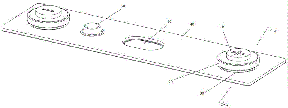
[0051] refer to Figure 1 to Figure 7, the embodiment of the present invention provides a power battery cover plate assembly, including a pole 10, an insulator 20, a composite flange 30 and a cover body 40; the above pole 10 includes a top end and a bottom end, between the top end and the bottom end The pole 10 is provided with a welding portion 11 protruding around the pole 10, the welding portion 11 includes a lower platform 113, a buffer wall 112 and an upper platform 111, the lower platform 113 is connected with the pole 10, and the lower ladder The side of the platform 113 away from the pole 10 is connected to the buffer wall 112, and the buffer wall 112 is also connected to the upper platform 111; The distance on the plane; the insulator 20 is provided with a pole installation hole, the bottom end of the pole 1...


PUM


Abstract

The invention discloses a cover board assembly for a power battery and the power battery. The power battery comprises poles, insulators, composite ring flanges and a cover board body, wherein a welding part which protrudes to surround each pole is arranged on the pole between the top end and the bottom end; each welding part comprises a lower terrace, a buffer wall and an upper terrace; each lower terrace is connected with the corresponding pole; one side, far away from the corresponding pole, of each lower terrace is connected with the corresponding buffer wall; each buffer wall is also connected with the corresponding upper terrace; and the distance from each upper terrace to the plane in which the top end of the corresponding pole is located is smaller than that from the corresponding lower terrace to the plane in which the top end of the corresponding pole is located; a pole installation hole is formed in each insulator; the bottom end of each pole extends along the corresponding pole installation hole and penetrates through the corresponding insulator; each upper terrace is in contact with the upper surface of the corresponding insulator to prevent the corresponding pole from further sliding towards the inside of the corresponding pole installation hole; the lower surface of each upper terrace and the upper surface of the corresponding insulator are hermetically welded; and each composite ring flange is connected with the corresponding insulator and the cover board body respectively. According to the cover board assembly of the power battery and the power battery, the use safety is improved; and the service lifetime is prolonged.

Description

technical field [0001] The invention relates to the field of power batteries, in particular to a power battery cover assembly and a power battery. Background technique [0002] As a key component of energy output for electric vehicles (pure electric and hybrid), lithium-ion power batteries are valued by various automobile manufacturers, battery manufacturers and energy storage and other new energy manufacturers. The power battery cover is the core component of the battery structure. The cover plate of a general lithium-ion power battery is composed of a cover body, a plastic gasket, a pole and a riveting sheet, which are connected together by riveting after injection molding, and plastic is used as a sealing and insulating material between the cover body and the battery pole. When used in different environments and extreme environments, plastics will shrink, age, and loose riveting, which will cause battery leakage and cause safety problems. [0003] In order to avoid safe...

Claims


Application Information

Patent Timeline
Patent Type & Authority Applications(China)
IPC IPC(8): H01M2/04H01M2/30H01M10/0525B60L11/18H01M50/147H01M50/172H01M50/543
CPCH01M10/0525B60L53/00H01M2220/20H01M50/147H01M50/148H01M50/543Y02E60/10Y02T10/70Y02T10/7072Y02T90/14
Inventor 杨子成
Owner SHENZHEN 3SUN ELECTRONICS
Learn More