
An adjustable hip joint testing machine loading system

A loading system and hip joint technology, applied in the mechanical field, can solve the problems of difficult control, loading lag, and high cost, and achieve the effects of improving work efficiency, improving accuracy, and simple structure

Inactive Publication Date: 2018-04-10
CHINA UNIV OF MINING & TECH
View PDF7 Cites 0 Cited by
  • Summary
  • Abstract
  • Description
  • Claims
  • Application Information

AI Technical Summary

Problems solved by technology

The signal of electromagnetic loading in the laboratory is easily disturbed by the external environment, and the loading force is relatively small and difficult to control; the response of the hydraulic loading system is slow, and the loading response is relatively lagging; the size of the traditional mechanical loading loading force is not easy to adjust, and the experimental efficiency is low.
[0004] In many tests and engineering applications, there are two problems: first, when the loading force is applied, the vibration of the motor has a great influence on the force of the hip joint, and the hip joint cannot be accurately measured. Stress situation
Second, in many cases, the performance of the hip joint material under different pressure conditions is required, but the general loading system can only provide a single loading force and cannot be adjusted
If the hip joint material is loaded by different loading systems, the cost is high and the efficiency is low

Method used


Image

  • An adjustable hip joint testing machine loading system
  • An adjustable hip joint testing machine loading system
  • An adjustable hip joint testing machine loading system

Examples


Embodiment Construction

[0029] The present invention will be further described below in conjunction with the accompanying drawings.

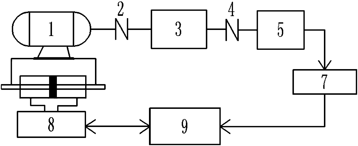
[0030] as attached figure 1 The Adjustable Hip Tester Loading System shown includes:

[0031] Power unit 1, used to generate test loading torque;

[0032] The loading force executing unit 5 is used to convert the torque into the loading force, and apply the loading force to the hip joint test material;

[0033] The magnetic coupling unit 3 is used to softly connect the power unit 1 and the loading force execution unit 5;

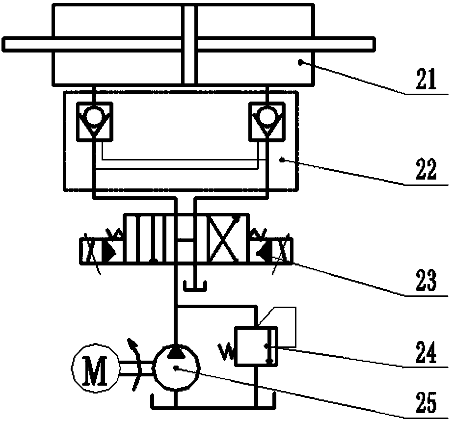
[0034] The hydraulic control unit 8 is used to drive the power unit 1 to perform feed movement, adjust the output torque of the magnetic coupling unit 3, and generate different loading forces;

[0035] The sensor detection feedback unit 7 is used to detect the real-time loading force and provide feedback for the micro-adjustment of the hydraulic control unit 8;

[0036] The main control unit 9 is used for collecting and analyzing the signal of th...


PUM


Abstract

The invention discloses an adjustable loading system for a hip joint testing machine, and relates to a comprehensive simulation loading system for testing the abrasion of hip joint materials under load. The system includes a power unit, a magnetic coupling unit, a loading force execution unit, a hydraulic control unit, a sensor detection feedback unit and a main control unit. The output torque of the power element is transmitted through the magnetic coupling, and the loading force execution unit converts the torque into the pressure acting on the material of the hip joint. At the same time, the hydraulic control unit can generate different loading forces by adjusting the air gap of the magnetic coupling unit, and provide stroke locking. The sensor detection feedback unit can detect the change of loading force in real time, and provide micro-adjustment deviation feedback to achieve accurate loading. The loading system reduces the impact of the vibration of the power motor on the loading force, and realizes continuous loading under different loads. The closed-loop loading system improves system reliability and accuracy, saves costs and improves efficiency.

Description

technical field [0001] The invention relates to a mechanical-electromagnetic-hydraulic composite simulation loading system, in particular to a device which needs to perform loading tests on different loading conditions, and belongs to the field of mechanical technology. Background technique [0002] The loading system of the testing machine is an important means to study the performance of the test material under a certain pressure. The hip joint testing machine can effectively simulate the movement rules of human joints, which is of great value and significance to the design and use of human bionic joints. Therefore, it is also of great significance to study the wear of hip joint test materials under certain loads. [0003] At present, there are different classifications of loading methods for testing machines, such as electromagnetic loading, hydraulic loading, and mechanical loading of transmission, according to the applied loading force. The signal of electromagnetic l...

Claims


Application Information

Patent Timeline
Patent Type & Authority Patents(China)
IPC IPC(8): G01N3/56G01N3/02
CPCG01N3/02G01N3/56G01N2203/0048
Inventor 程刚郭锋山显雷乔智刘相镇胡媛媛周振中
Owner CHINA UNIV OF MINING & TECH
Learn More