Rupture test buffering device of steel wire rope tension testing machine

A tensile testing machine and buffer device technology, applied in measuring devices, using stable tension/pressure testing material strength, instruments, etc., can solve problems such as affecting work performance, guide screw breakage, screw breakage and scattering, etc. The effect of ensuring normal operation, reducing device vibration and preventing breakage

Inactive Publication Date: 2016-06-22
UNIV OF JINAN
View PDF8 Cites 2 Cited by
  • Summary
  • Abstract
  • Description
  • Claims
  • Application Information

AI Technical Summary

Problems solved by technology

In the tensile test, when the tensile force of the steel wire rope is greater than its own tensile strength and suddenly breaks, the piston rod of the hydraulic cylinder of the tensile testing machine will instantly impact the front top beam under the action of hydraulic oil, causing the guide screw at the connection between the force ball head and the force seat The instantaneous tension is too large and it breaks, which makes the tensile testing machine unable to work normally.
[0003] The working environment of the testing machine is relatively harsh. The long-term exposure of the force ball head, force seat, and guide screws will cause sand and dust to adhere to it, which will affect its working performance. When the wire rope breaks, the guide screws will break and scatter, causing damage to personnel or equipment.

Method used


Image

  • Rupture test buffering device of steel wire rope tension testing machine
  • Rupture test buffering device of steel wire rope tension testing machine
  • Rupture test buffering device of steel wire rope tension testing machine

Examples


Embodiment Construction

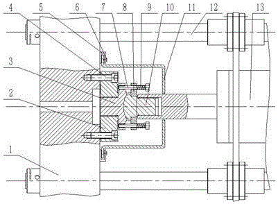
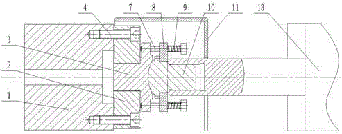
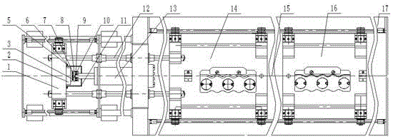
[0015] The present invention will be described in detail below in conjunction with accompanying drawing: figure 1 , figure 2 , image 3 As shown, a breaking test buffer device for a wire rope tensile testing machine, the main structure includes a hydraulic cylinder 13, a force applying ball head 10, a pull plate 8, a force applying seat 3, a sensor 2, a front top beam 1, a spring 9, a guide screw 7, an inner Hex screw 4, protective cover 11, guide positioning plate 5, screw 6, described sensor 2 is fixed on the described front top beam 1 by described hexagon socket screw 4, described force applying ball head 10, force applying seat 3 are respectively connected with the piston rod of the hydraulic cylinder 13 and the sensor 2 through a thread structure, the pull plate 8 is set on the force applying ball head 10, and the six uniformly distributed guide screws 7 pass through the The pull plate 8 connects the force application ball head 10 and the force application seat 3, and ...


PUM


Abstract

The invention provides a rupture test buffering device of a steel wire rope tension testing machine. The rupture test buffering device mainly comprises a hydraulic cylinder, a force applying spherical head, a pull disc, a force applying seat, a sensor, a front top beam, springs, guide screws, an inner hexagonal screw, a protective cover, a guide positioning plate and a screw, wherein the sensor is fixed on the front top beam through the inner hexagonal screw; the force applying spherical head and the force applying seat are connected with a piston rod of the hydraulic cylinder and the sensor through thread structures respectively; the pull disc sleeves the force applying spherical head; the six guide screws, which are uniformly distributed, are used for connecting the force applying spherical head and the force applying seat through the pull disc; the six springs sleeve the six guide screws respectively and are located between the pull disc and the heads of the guide screws; the guide positioning plate is welded on the front top beam; and the protective cover is embedded into the guide positioning plate and is tightly clamped by the screw. When a steel wire rope is suddenly ruptured in a tension test, the tension to the guide screws is reduced through compression and energy storage properties of the springs when the front top beam is subjected to instant impact, so that the guide screws are prevented from being broken and the normal operation of the device is guaranteed.

Description

technical field [0001] The invention relates to a device for a tensile testing machine, in particular to a breaking test buffer device for a steel wire rope tensile testing machine. Background technique [0002] Steel wire ropes are mainly used in lifting, traction and other occasions, and the working conditions are relatively harsh. During use, friction and wear, fatigue damage, local broken wires and deformation will occur, which reduces the tensile strength of the steel wire rope. In order to ensure the reliability of the steel wire rope for repeated use, it is necessary to carry out a tension test in accordance with the relevant national standards. In the tensile test, when the tensile force of the steel wire rope is greater than its own tensile strength and suddenly breaks, the piston rod of the hydraulic cylinder of the tensile testing machine will instantly impact the front top beam under the action of hydraulic oil, causing the guide screw at the connection between t...

Claims


Application Information

Patent Timeline
IPC IPC(8): G01N3/02G01N3/10
CPCG01N3/02G01N3/10
Inventor 崔卫华客圣俊赵萍赵霞付超
Owner UNIV OF JINAN
Why Eureka
Try Eureka