
Machine tool guide rail installation plane parallelism quick measurement device and method

A technology for installing planes and measuring devices, applied to measuring devices, electrical devices, instruments, etc., can solve the problems of complex operation, high price, and unsuitability for large-scale applications, and achieve the effects of ensuring measurement accuracy, simple device structure, and reducing errors

Inactive Publication Date: 2016-06-22
XI AN JIAOTONG UNIV +1
View PDF8 Cites 8 Cited by
  • Summary
  • Abstract
  • Description
  • Claims
  • Application Information

AI Technical Summary

Problems solved by technology

Among these testing tools, the dial indicator can only be used in the case of a small guide rail plane spacing, while the level and autocollimator need to use a bridge plate during the measurement process, which is not suitable for the narrow surface and special position of the guide rail installation surface use
In addition, the optical measurement method has high requirements on the surface to be measured, the prism itself and its moving guide rail, and it is difficult to use it conveniently in the machine tool production site
Although the laser interferometer has high measurement accuracy, it is expensive and complicated to operate, so it is not suitable for a large number of applications

Method used


Image

  • Machine tool guide rail installation plane parallelism quick measurement device and method
  • Machine tool guide rail installation plane parallelism quick measurement device and method
  • Machine tool guide rail installation plane parallelism quick measurement device and method

Examples


Embodiment Construction

[0034] The present invention will be described in further detail below in conjunction with the accompanying drawings.

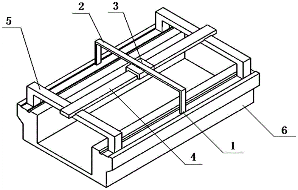
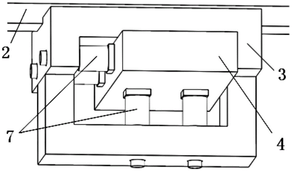
[0035] see Figure 1-4 , the present invention machine tool guide rail mounting plane parallelism fast measuring device comprises four eddy current sensors 1, sensor mounting bracket 2, slide block 3, flat ruler slide rail 4, measuring system bracket 5, tested machine bed 6. Among them, the machine bed 6 to be tested needs to be fixed on the ground with fastening screws and leveled before it is measured; the two measurement system brackets 5 are installed on the guide rails of the machine bed 9 to be tested. The plane is clamped by the wedge block so that it is close to the side and bottom surface of the guide rail installation plane; the marble-made flat ruler slide rail 4 is placed in the limit groove above the measurement system bracket 5 so that it is in line with the measured machine bed The installation planes of the guide rails 6 are basically paralle...


PUM


Abstract

The invention discloses a machine tool guide rail installation plane parallelism quick measurement device and method, and the device comprises a sensor installation support and two measurement system supports, wherein the two measurement system supports are used for supporting the sensor installation support through leveling ruler sliding rails. The two measurement system supports are fixed on a machine tool guide rail installation plane, and the central lines of the two measurement system supports are coincided with the central line of the sensor installation support. A sliding block is disposed between the sensor installation support and the leveling ruler sliding rails, is fixed with the sensor installation support and drives the sensor installation support to move along the leveling ruler sliding rails. The sensor installation support is provided with electric vortex sensors, and the probes of the electric vortex sensors respectively face a side surface and a bottom surface in the machine tool guide rail installation plane. The method comprises the steps: support installation, sensor signal collection, sliding block movement, measurement circulating, and data processing. The electric vortex sensors are used for collecting data at different positions, and the parallelism error of the machine tool guide rail installation plane is fit. The device is simple in structure, is simple and convenient to operate, is small in testing result error, and is high in precision.

Description

technical field [0001] The invention belongs to the field of machining and detection of machine tool guide rails, and in particular relates to a fast measuring device and method for measuring the parallelism of machine tool guide rail installation planes. Background technique [0002] As an important part of the machine tool, the parallelism error of the guide rail will directly affect the final performance of the machine tool. The parallelism of the guide rail is largely affected by the machining accuracy of the guide rail installation plane. Therefore, it is necessary to accurately and efficiently measure and control the parallelism error of the machine tool guide rail installation plane. In actual production, due to the special position of the installation plane of the machine tool guide rail and the narrowness of the measured surface, the existing detection tools cannot detect it quickly, accurately and effectively, and new detection tools need to be developed. [0003...

Claims


Application Information

Patent Timeline
Patent Type & Authority Applications(China)
IPC IPC(8): G01B7/30
CPCG01B7/30
Inventor 贾书海郭凯宋晓波蒋太权梅雪松陈花玲杨红军
Owner XI AN JIAOTONG UNIV
Learn More