
Multifunctional suction machine

A suction machine and multi-functional technology, which is applied in the direction of conveyors, conveying bulk materials, transportation and packaging, etc., can solve the problems of low production efficiency, achieve the effects of reducing transportation costs, flexible and convenient use, and benefiting production efficiency

Active Publication Date: 2018-06-29
刘跃
View PDF4 Cites 0 Cited by
  • Summary
  • Abstract
  • Description
  • Claims
  • Application Information

AI Technical Summary

Problems solved by technology

[0004] The purpose of the present invention is to provide a multi-functional suction machine with simple structure and satisfying continuous production requirements, so as to solve the problem that the traditional suction machine needs to turn off the fan to take materials from the storage bin, which leads to low production efficiency.

Method used

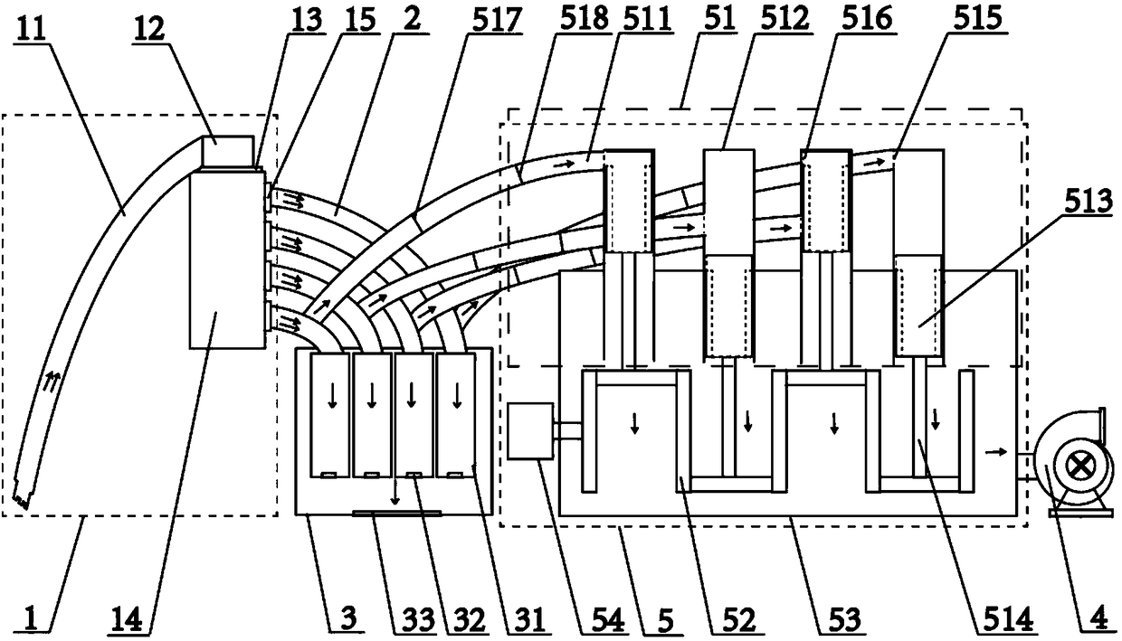

Image

  • Multifunctional suction machine
  • Multifunctional suction machine

Examples


Embodiment Construction

[0025] In order to make the purpose, technical solution and advantages of the present invention clearer, the technical solution of the present invention will be clearly and completely described below. Apparently, the described embodiments are only some of the embodiments of the present invention, but not all of them. Based on the embodiments of the present invention, all other embodiments obtained by persons of ordinary skill in the art without making creative efforts belong to the protection scope of the present invention.

[0026] In the description of the present invention, it should be noted that the terms "center", "upper", "lower", "left", "right", "vertical", "horizontal", "inner", "outer" etc. The indicated orientation or positional relationship is based on the orientation or positional relationship shown in the drawings, and is only for the convenience of describing the present invention and simplifying the description, rather than indicating or implying that the refe...


PUM


Abstract

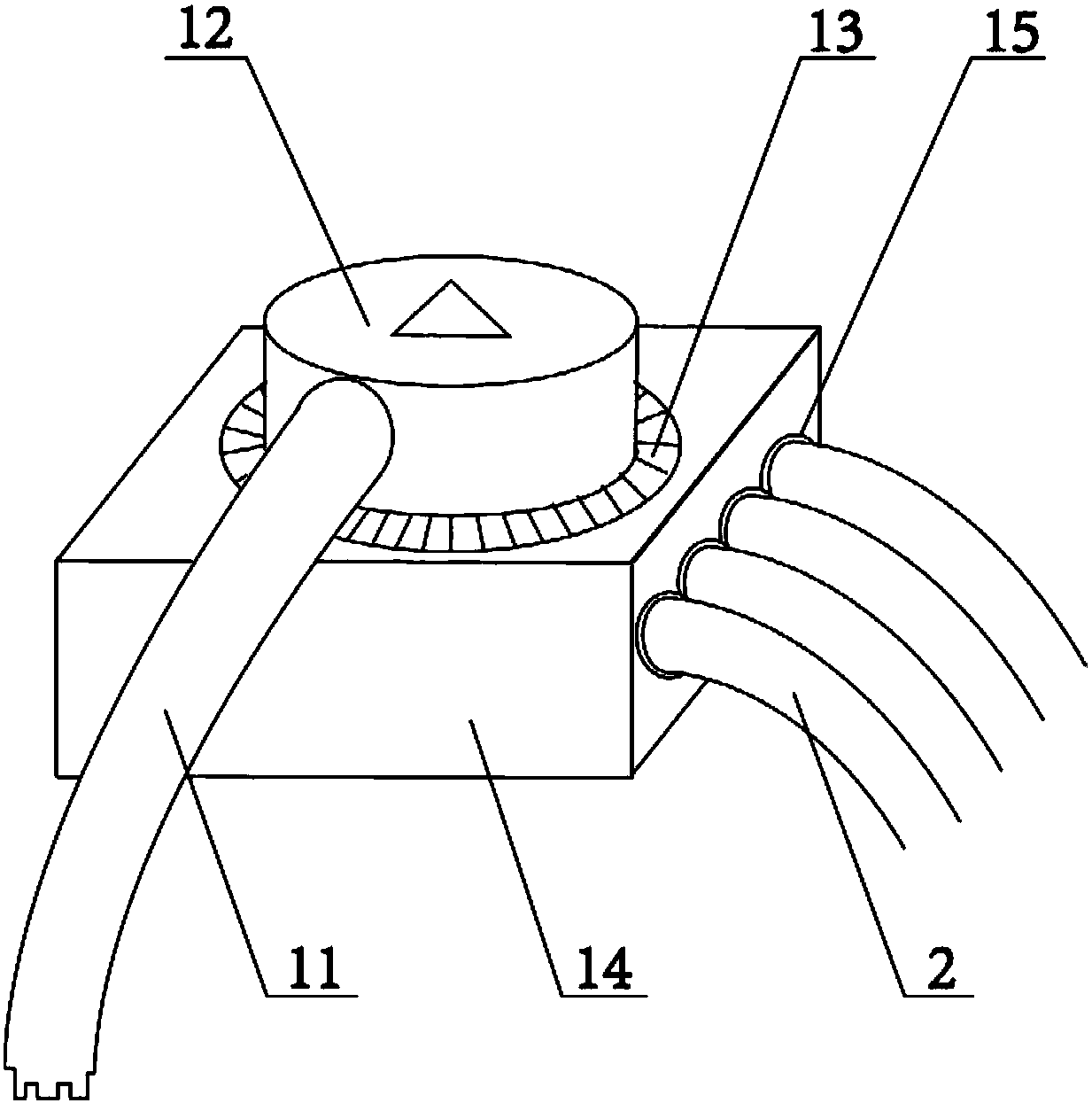
The invention relates to the field of mechanical conveying equipment, in particular to a multifunctional object suction machine. The multifunctional object suction machine comprises an object suction unit, dispersion pipelines, a storage box, a pressure conduction unit and a draught fan. The object suction unit is connected with the storage box through the dispersion pipelines. Air way pipelines are arranged on the pressure conduction unit and connected with the dispersion pipelines. The pressure conduction unit is connected with the draught fan and comprises communicating devices, a cam shaft, a pressure conduction bin and a motor. Each communicating device comprises the corresponding air way pipeline, an air cylinder, a piston and a piston rod. According to the multifunctional object suction machine, by the adoption of the communicating devices capable of alternately communicating with the pressure conduction bin, the dispersion pipelines and storage bins corresponding to the dispersion pipelines, under the condition that the draught fan of the object suction machine is not turned off, continuous suck-in and take-out of materials are achieved; and compared with a traditional conveying device, the requirement for continuous production can be met, production efficiency can be improved, meanwhile, the loss generated when the draught fan is turned on and turned off frequently can be reduced, energy is saved, and transportation cost is lowered

Description

technical field [0001] The invention relates to the field of mechanical conveying equipment, in particular to a multifunctional suction machine. Background technique [0002] There are many types of devices that use gas to transport materials, including suction type, pressure type and hybrid type. Its working principle is to use the kinetic energy of the airflow to make the granular material in a suspended state and transport along the pipeline with the airflow. Among them, the suction type material conveying device, also known as negative pressure conveying device, is to make the whole conveying system have a certain degree of vacuum when the air induction device at the end of conveying is in operation. Under the power of the internal and external pressure difference, the outside air is sucked At the same time, the material is brought into the pipeline with the movement of the air, and sent to the separator at the discharge place along the conveying pipe. After the materia...

Claims


Application Information

Patent Timeline
Patent Type & Authority Patents(China)
IPC IPC(8): B65G53/24B65G53/36
CPCB65G53/24B65G53/36
Inventor 刘跃
Owner 刘跃
Learn More